Custom Diagram Types
You can create extended diagram types in Enterprise Architect and include them in MDG Technologies. To do this, perform the following steps.
| 1. | Create a profile with the same name as the MDG Technology in which it is to be included; e.g. "SysML". |
| 2. | Create a «stereotype»Class element which is named as the custom diagram, e.g. "BlockDefinition". |
| 3. | Create a Class element and name it as one of the Built-In Diagram Types prefixed with "Diagram_", for example 揇iagram_Logical?for class diagrams or 揇iagram_Use Case?for use case diagrams. |
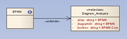
| 4. | Give the Diagram_x class the «metaclass» stereotype and draw an «extends» connector from the stereotype to the metaclass. |
| 5. | Give the stereotype class a brief description in the 揘otes?field of what the diagram is used for. This description displays in the bottom right-hand corner of the 揘ew Diagram?dialog. |
| 6. | Give the Diagram_x class the following attributes as required: |
| · | diagramID: string = abc (where "abc" is the diagram type that appears on the diagram frame label). |
| · | toolbox: string = ToolboxName (where "ToolboxName" is the name that appears in the toolbox heading for the toolbox that you want to open automatically each time a diagram is opened). |
| · | frameString: string = FrameFormatString (where "FrameFormatString" is a string containing substitution macros for defining the frame title, with or without additional delimiters such as []. Macros that can be used are: |
| · | styleex: string = TConnectorNotation=Option; (where "Option" is one of "UML 2.1", "IDEF1X", or "Information Engineering"). |
The following example shows the BPMN diagram profile which defines a BPMN diagram as an extension of the Enterprise Architect Analysis diagram.
| 7. | Save the diagram as a profile in the usual manner. |
| 8. | If you are using the MDG Technology Wizard with an MTS file to generate your technology, edit the MTS file to get the DiagramProfile generated into your technology file. Inside the root <MDG.Selections> node insert the following. |
<DiagramProfile directory=擬yPath?files=擬yFile1.xml,MyFile2.xml?>
Where MyPath is the directory your DiagramProfile is saved in, and MyFile1.xml and MyFile2.xml are the diagram profiles to include in this technology.


