


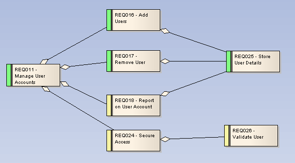
A Requirements diagram is a custom diagram used to describe a system's requirements or features as a visual model.
Requirements are defined using Requirement elements (Custom elements of type Requirement). To view the detailed description of a Requirement, double-click on the element to display its properties. Requirement elements can be linked back to Use Cases and Components in the system to illustrate how a particular system requirement is met.
Requirements models provide extensions to the UML model and enable traceability between specifications and design requirements, and the model elements that realize them.
Requirements can have relationships with other elements such as other Requirements and Use Cases. To view the traceability of a requirement, use the Hierarchy window, which you access using the View | Hierarchy menu option (or press [Ctrl]+[Shift]+[4]).
Toolbox Elements and Connectors
Select Requirements diagram elements and connectors from the Requirements pages of the Enterprise Architect UML Toolbox.
Tip: Click on the elements and connectors below for more information.
Requirements Diagram Elements |
Requirements Diagram Connectors |
|
|
|
|
|
|
|
|