


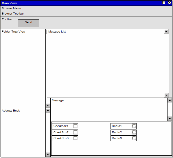
User Interface Diagrams are custom diagrams used to visually mock-up a system's user interface using forms, controls and labels.
In the example User Interface diagram below, forms, controls and labels are arranged on the diagram to describe its appearance. UI elements can also be traced to other model elements linking the UI with the underlying implementation.
Toolbox Elements and Connectors
Select User Interface diagram elements and connectors from the User Interface pages of the Enterprise Architect UML Toolbox.
Tip: Click on the elements and connectors below for more information.
Requirements Diagram Elements |
Requirements Diagram Connectors |
|
|
|
|
|
|
|
|