| [ Team LiB ] |
|
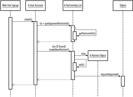
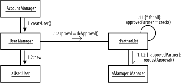
2.6 Interaction DiagramsClass diagrams are not well suited to describing program flow. While modelers frequently use class diagrams to model aspects of systems that are oriented towards process instead of data, seeing the internal class relations does not always translate into a clear view of the underlying logic. All modeling systems have some mechanism for indicating the flow of control between multiple objects in the system. In the UML, these diagrams are referred to as interaction diagrams. There are two kinds of interaction diagrams: sequence diagrams and collaboration diagrams. 2.6.1 Sequence DiagramsSequence diagrams, which show the sequential interactions of a set of objects, are the most common kind of interaction diagram. They can be used for understanding the flow of control within an application (or more often, given the scale of the average enterprise system, within a component of the system). Sequence diagrams consist of a row of boxes representing objects, generally placed from left to right in order of their appearance within the flow of control. These are the same boxes used for object diagrams with the labels underlined to indicate that they are objects rather than classes. A lifeline stretches down from each object. The lifeline begins when the object is created and ends when the object is removed. If the object is never removed, the lifeline continues to the bottom of the page. Each lifeline contains one or more activation boxes. Activation boxes show that the object is actively processing, or blocking, while waiting for a response from further down the line. When modeling classes directly, activation boxes correspond to the duration of a method invocation on the object. Figure 2-15 shows how an object representing the signup process for our hypothetical web site would go about creating a user account, associating it with a partner object, and requesting account approval from a manager. The sequence begins by calling a method on the web site signup object, which creates a user account. The newly created user account determines the level of access it is authorized to have, checking a partnership list and creating a new partner object if none is found. Creating a new partner kicks off an asynchronous request for a manager to review the new account. Figure 2-15. Sequence diagram The arrows connecting the activation boxes represent messages sent between the objects. These may be local method calls, remote object invocations, intersystem messages sent via SOAP or JMS, or any other kind of inter-object communication. The solid arrow with the solid arrowhead represents a standard message, and the dashed arrow with an open arrowhead represents a message return. Standard messages imply a return; in many cases, you can leave the explicit return off the diagram entirely, reducing overall clutter. Finally, solid arrows with half of an open arrowhead (such as the one in the bottom righthand corner) represent asynchronous messages. Asynchronous messages, obviously, have no returns. Each message can and should be labeled. At the minimum, the label will identify the type of message sent. Figure 2-15 labels messages with the name of the method invoked. When the message creates a new object, the message is labeled as "new." Some messages include criteria surrounded by brackets. These are conditions that must be satisfied for the message to be sent. There is no specific format for conditions, but, obviously, they should be written so as to be readable. Messages marked with an * are considered iterative. In Figure 2-15, the getPartnerInfo( ) method will be called repeatedly until all partner information has been received. Constraints on the message can be used to further tighten the loop. Objects can send messages to themselves, a process that is akin to invoking a local method. In this case, the message arrow just doubles back towards the activation box, and a second activation box is added to the side of the first box. 2.6.2 Collaboration DiagramsSequence diagrams make the order of operations clear, but they don't lend themselves to particularly flexible layouts or provide a clear picture of the static relationships between classes or objects. Like sequence diagrams and object diagrams, collaboration diagrams are built around object boxes. As in sequence diagrams, objects are connected via messages, but lifelines are not used. Instead of tracking time from top to bottom, we assign a number to each inter-object message. In simple diagrams, the numbering sequence can be 1,2,3...n, which makes it easy to see where each message plays into the collaboration. Messages in collaboration diagrams can also be numbered in outline form. When numbering messages in this way, the first message sent is numbered 1. The next message sent by the same object, after the completion of message number 1, is message number 2. However, if the recipient of message number 1 sends out an additional message in the course of responding to message number 1, that message is labeled 1.1. The first message sent by the recipient of 1.1 is 1.1.1, and so forth. Figure 2-16 shows a collaboration diagram similar (but not identical) to the sequence diagram in Figure 2-15. The messages sent between objects are all procedure calls and are labeled with either the method name or the assignment performed. Some messages have conditions presented in square brackets, such as the [! approvedPartner] condition that launches an asynchronous request for approval to a manager object. In this diagram, the user object will be created anyway and the Manager object will presumably update it later, after manual approval. Figure 2-16. Simple collaboration diagram with outline numbering This diagram also contains a loop-back in 1.1.1, represented by a line arching back into the object and a conditional beginning with an asterisk (*). |
| [ Team LiB ] |
|