|
|
|
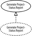
6.1 RolesAs discussed in Chapter 2, the object-oriented paradigm views the world as a collection of unique elements (objects, classes, subsystems, and so forth), often referred to as a society of objects, which communicate with one another. Communication from a sender element to a receiver element is used to convey information or request processing. The word "objects" is used in the phrase "society of objects" rather than "classes," "subsystems," or any other word, because objects are the most fundamental, or primitive, parts of the object-oriented paradigm. It is also common to use the phrase "society of elements." For example, Figure 6-1, a use-case diagram, shows that a project manager may request that the project management system generate a project-status report that is sent to a printer. The Generate Project-Status Report use case involves a Project Manager actor who initiates the generation of the report and a Printer actor through which the report is printed, as discussed in Chapter 4. Figure 6-1. Generating a project-status report The Generate Project-Status Report use case may have the following description:
Notice how all the actors and the system are involved in this description. The description indicates that the system will generate the report, but it does not indicate how. To provide the functionality for the report, a society of objects must work together in much the same way the classes in Figure 6-2 do. Figure 6-2 shows that an organization may execute any number of projects. An object of the Organization class may contain zero or more objects of the Project class, and each object of the Project class must be contained by no more than one object of the Organization class, as discussed in Chapter 3. Therefore, these classes and others could be used to form a society of objects that work together to provide the functionality of the Generate Project-Status Report use case. Figure 6-2. Organizations and projects As the classes in Figure 6-2 may interact and collaborate with other classes to provide the functionality in Figure 6-1, each class or association may play a role within that interaction and collaboration. A role is a placeholder for an object or link to play in an interaction and collaboration. Elements that play such roles are known as participating elements. For example, the participating elements in the Generate Project-Status Report use case may play the following roles:
To generate the report in an interaction and collaboration, I can use an object of the Project class to access information about the project directly, or I can use a link of the Execute association as a means to access an object of the Project class. Because I want to demonstrate how to use classes and objects as well as associations and links in interactions and collaborations, I will focus on the Organization class and Execute association rather than the Organization class and Project class. In the UML, the use of an interaction and collaboration is depicted as a dashed ellipse containing the name of the interaction and collaboration. The interaction and collaboration may be attached to the use case that it realizes using a realization relationship, as discussed in Chapter 3. Figure 6-3, a use-case diagram, shows that the Generate Project-Status Report interaction and collaboration realizes the Generate Project-Status Report use case. It is quite common to use the same name for the interaction and collaboration as the use case it realizes. Figure 6-3. Interaction and collaboration realizing a use case The Generate Project-Status Report interaction and collaboration may have the following description using the initiator, output device, project organization, and project reference roles just described:
Notice how all the roles and other elements are involved in this description. The description elaborates on the Generate Project-Status Report use case and indicates how the system will generate the report:
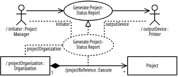
The roles in the Generate Project-Status Report interaction and collaboration can be classified as class roles and association roles. 6.1.1 Classes and ObjectsA class role defines a specific use of an object of a class; objects of the class are said to conform to the class role. For example, a project manager plays the role of an initiator, a printer plays the role of an output device, and an organization plays the role of an organization that contains the project that is the subject of a project-status report. To show that objects of a class conform to a class role, a dashed line is drawn from the interaction and collaboration symbol to the class and labeled with the role objects of the class play in the interaction and collaboration. For example, Figure 6-4, a diagram that uses elements from a use-case diagram and a class diagram, combines Figures Figure 6-1 through Figure 6-3 to show the initiator, outputDevice, and projectOrganization class roles. Figure 6-4. Interaction and collaboration using classes In addition, Figure 6-4 demonstrates two methods for identifying a role. One method involves labeling the dashed line to indicate that objects of a class conform to a role. You may also show a class using the notation for classes as defined in Chapter 3, but with the class name preceded by a forward slash followed by the name of the role followed by a colon梖or example, /projectOrganization:Organization. The forward slash indicates that the name to follow, projectOrganization, is a rolename. That is followed by a colon and, finally, the class name, which in this case is Organization. Usually, you will want to use just one of these methods consistently. To show that a specific object of a class conforms to a class role, a dashed line is drawn from the interaction and collaboration symbol to the object and labeled with the role the specific object of the class plays in the interaction and collaboration. As with a class, rather than label the dashed line, you may show an object using the notation for objects as defined in Chapter 3, but the object name is followed by a forward slash followed by the name of the role followed by a colon followed by the class name, all fully underlined. For example, Figure 6-5, which is a diagram that uses the elements from a use-case diagram and an object diagram, shows that Andy plays the role of an initiator, Andy's printer plays the role of an output device, and Andy's organization plays the role of an organization that contains the project that is the subject of the report. Figure 6-5. Interaction and collaboration using objects 6.1.2 Associations and LinksAn association role defines a specific use of a link of an association. Links of the association are said to conform to the association role. For example, an execute relationship plays the role of a reference to the project that is the subject of a project-status report. To show that links of an association conform to an association role, a dashed line is drawn from the interaction and collaboration symbol to the association and labeled with the role links of the association play in the interaction and collaboration. Also, rather than label the dashed line, you may show the association using notation similar to that used for classes in Figure 6-4: the association name is preceded by a forward slash followed by the name of the role followed by a colon. For example, Figure 6-6 updates Figure 6-4 and shows the projectReference association role. Figure 6-6. Interaction and collaboration using associations To show that a specific link of an association conforms to an association role, a dashed line is drawn from the interaction and collaboration symbol to the link and labeled with the role the specific link of the association plays in the interaction and collaboration. Also, rather than label the dashed line, you may show the link using notation similar to that used for objects in Figure 6-5: the association name is preceded by a forward slash followed by the role followed by a colon. Recall from Chapter 3 that a link may have its association name shown near the path fully underlined, but links do not have instance names. For example, Figure 6-7 updates Figure 6-5 and shows the projectReference link role. Figure 6-7. Interaction and collaboration using links |
|
|
|