In order to provide a scalable and reliable platform, you can adopt various strategies. Scale up and scale out are the two common categories that these strategies fall under. Scale up basically means adding more hardware, or better performing hardware, to a single server. You could add more RAM or more and stronger CPUs, for example. Scale out means that you distribute your workload on many servers. Here you find Network Load Balancing (NLB) and Microsoft Cluster Service (MSCS), described earlier in the book.
Let us start by looking at ways of scaling up Windows. Before you simply add more RAM or more CPUs, you need to consider what Windows version you are using or planning to use. It would be a waste to add four CPUs to a Windows Server 2003 Web Edition system, for instance, since it only supports two CPUs in the first place. As you can understand, this is also why it is so important to carefully consider the platform you are going to use for the different parts of your system early in the design process. You want to neither under- nor over-dimension it. It is also important to consider future needs of the system so you can easily scale up later on, with minimum cost and without the need to purchase a new license for the operating system.
With the addition of the Windows Server 2003 family, Microsoft offers a wide assortment of operating systems that can scale from 1 CPU all the way to 64. Table 4-4 shows an overview of the basic scaling-up possibilities in the Windows 2000 Server and Windows Server 2003 families.
|
Server Edition |
Max RAM |
Max CPUs |
|---|---|---|
|
Windows 2000 Server |
4GB |
4 |
|
Windows 2000 Advanced |
8GB |
8 |
|
Windows 2000 Datacenter |
64GB |
32 |
|
Windows Server 2003 Web |
2GB |
2 |
|
Windows Server 2003 Standard |
4GB |
4 |
|
Windows Server 2003 Enterprise |
32GB |
8 |
|
Windows Server 2003 Enterprise 64-bit |
64GB |
8 |
|
Windows Server 2003 Datacenter |
64GB |
64 |
|
Windows Server 2003 Datacenter 64-bit |
512GB |
64 |
In some cases it is not enough just to rely on scaling up. It might not even be the best way to increase performance. Your Web clusters, for example, benefit more from scaling out than from scaling up. It is better to let more Web servers handle client requests than to have one huge server becoming a single point of failure. Database systems and messaging systems can benefit from both ways of scaling, as you will see later. Table 4-5 shows how you can scale out the Windows Server families.
|
Edition |
NLB Nodes |
Cluster Support |
Cluster Nodes |
Comments |
|---|---|---|---|---|
|
Windows 2000 Server |
32 |
NLB |
Only with Application Center |
|
|
Windows 2000 Advanced |
32 |
NLB/MSCS |
2 | |
|
Windows 2000 Datacenter |
32 |
NLB/MSCS |
4 | |
|
Windows Server 2003 Web |
32 |
NLB | ||
|
Windows Server 2003 Standard |
32 |
NLB | ||
|
Windows Server 2003 Enterprise |
32 |
NLB/MSCS |
8 | |
|
Windows Server 2003 Datacenter |
32 |
NLB/MSCS |
8 |
You can easily see that you have to carefully consider which Windows version to use during the design phase. We have said so before, but this is more important than many developers and designers think it is. You need to estimate the load, and the possibility of the load increasing over time, early on. Although the scaling features make it easy to add more power, you do not want to plan to have more expensive license fees in your system than you have to from the beginning. You do not want to implement a Web cluster based on Windows Server 2003 Standard Edition, unless you really need one of its features. The Web Edition is sufficient in most cases. It would also be unfortunate if you implement your database server on the Windows Server Standard Edition, and later on found out you need to cluster it with MSCS. Then you would have to spend money on an upgrade of the operating system and would probably end up with the completely unnecessary cost incurred by having both the Standard and the Enterprise Editions. That is just a waste of money you can avoid if you spend time on the design.
You should really consider the level of reliability and availability you need. If you are implementing a database system, can you possibly accept several minutes of disrupted service while you do a restore of a backup? If the answer is yes, go with the Windows Server 2003 Standard Edition. If the answer is no, you need something more powerful, like the Enterprise Edition or Datacenter Edition.
Do you need your services up and running constantly? That is another crucial question, since it affects the choice of both platform and cluster solution.
A cluster with MSCS is often used for a database or messaging system. There are several ways of setting up such a system. This kind of cluster consists of two or more nodes—that is, two or more independent servers. A node can be either active (it is handling requests) or passive (the node is standing by in case an active node fails).
You need to carefully consider whether a node in your cluster should be active or passive. Why? Well, if an active node encounters an error and fails while a passive node is available, you can let that node take the failing node's place without many problems. (This is based on the assumption that the passive node has the same, or better, hardware configuration as the failing node.)
You can also have a situation where all nodes are active in the cluster. If one node fails, applications and services can be transferred to another node. Then the load on the failover node will increase because it needs to handle the load of the failing node as well as its own. You do not want to under-dimension the hardware in this case, because if you do, the failover node might give in to sheer pressure and fail as well.
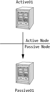
To better understand how you can use active and passive nodes, have a look at Figure 4-11. This figure shows two nodes, of which is active (Active01), with Passive01 standing by in case Active01 fails.
The average workload on the active node is a maximum of 45 percent CPU and memory resources. If Active01 fails, Passive01 takes its place and still has the resources left for peaks in the workload. This gives you time to fix the problems on the failing node, take it back online, and then fail back from the failover node.
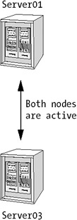
In a scenario such as Figure 4-12, you do not have a passive node that awaits a failing node. To make sure failover is successful in this case, you must configure the servers so the workload is proportional on the average. In this scenario, the failover has been configured to go from Server01 to Server03. Let us say Server01 has an average workload of 50 percent and Server03 has an average workload of 25 percent.
In this example, all servers have identical hardware configuration. If Server01 fails and Server03 takes its place, the new load on Server03 would be 75 percent. This does not leave much room for workload peaks. An even worse scenario would be if both servers averaged 50 percent of the workload. Then a failover server would have a 100 percent workload in case of a failure. The server could quite easily give in, giving you limited use of your cluster solution.
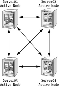
Another scenario would be if you configured your nodes to be able to fail over to any of the other servers in the cluster (see Figure 4-13). If they each had a workload of 35 percent, you could easily handle one failing server. The failover node would be working at 70 percent, but it could still handle requests. If another node fails and the same failover node had to handle this load too, it would be working well over 100 percent capacity, which would bring it down. The last node would probably die of a heart attack, even before it could try to handle the load. This would leave you with a nonworking cluster.
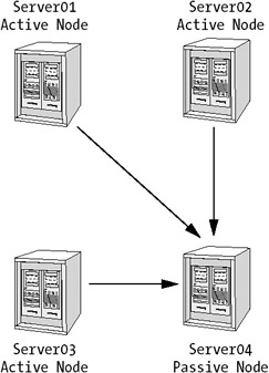
The scenario shown in Figure 4-14 is a common setup in many enterprises. In this case, you have set up your four-node cluster to have one passive node only. You have configured it to be at least twice as powerful as any of the other three servers. The workload on the three active nodes is 35 percent on average. If any of the active servers fail, the passive node would step in to take its place. Since it is a powerful server, it would have less workload than the failing node, making it prepared to handle one or more failing servers.
Most companies do not even have a more powerful passive server, since the likelihood of more than one server failing is small. But be aware that this is a calculated risk. The worst-case scenario could make the whole cluster fail.
These examples try to illustrate the importance of designing the cluster solution in a good way. The solution will be different depending on what problems need to be solved. You must consider the following, however:
How many nodes should you use?
What hardware configuration do you need?
How should you use active/passive nodes?
How much workload should the nodes have?
When you have a server cluster like the ones described in the previous section, data must be shared between applications running on the nodes. You would not have much use of a failover cluster node if it was unaware of the updates made by the failing node before the failure. This is often solved by using what is called a shared-nothing database configuration. This means that each server in the cluster owns a subset of the resources, and no server in the cluster owns the same subset at the same time as another. If there is an error and one server goes down, you can configure the cluster so that another (predefined) server takes ownership of the resources the failing server owned.
All data is placed on a common disk array, which could be connected over a SCSI cable or a fiber optic cable, or via a Storage Area Network (SAN). If a node fails, the data is still accessible to the failover node.
When you have many active nodes, often each is set up with a specific view into the database. This allows the various nodes to handle specific types of requests. Say you have a cluster handling the database of customer accounts. One server would have a view into the database for all accounts between A through F, another would handle G through K, and so on. The only node that could update an account is the active node responsible for this section of the database. This setup eliminates the possibility of having multiple nodes updating the same account.
You could still encounter an error to the shared data, however. So you need to plan the redundancy of this as well. Most common is using a RAID disk configuration, which would provide fault tolerance of various levels, depending on which RAID was chosen. This book will not cover RAID configurations, as this is out of the scope of our topic.
When a node is active, its resources are available. The clients, however, do not access the node in itself. That would not be a good solution, because if the node should fail, you would have to change the configuration of the clients so they access the failover node instead. The solution to this is to configure virtual servers. As long as the clients access the virtual server, it does not matter whether node A, B, C, or D services its requests. That is an internal cluster problem instead, and this solution is much more preferable than changing all clients.
A virtual server specifies groups of resources that fail over together. When a cluster server fails, all groups of resources on it marked for clustering fail over to another node. When the failed server has been fixed, you take it back online again. If you have configured your server cluster to do so, failback to the original server takes place. You could also configure the current server to continue processing requests, however, and make the fixed server become a passive node instead.
Let us take a look at resource groups. In a resource group, you collect, or associate, resources that are related to or dependent on each other. When you choose which applications to be a part of a resource group, you should consider its need for high availability. If your users require the application constantly, it should be a part of a resource group. If it is not, it can still run on the cluster server, but you would not have high availability for it.
Unfortunately, just adding any application to a resource group will not do. The application needs to be able to handle a cluster environment; otherwise it would not benefit from clustering. Applications that can work within a cluster environment are said to be cluster aware. They have built-in features that let them register with the server cluster, so they can receive cluster status and notification information. SQL Server and Microsoft Exchange Server are both cluster-aware applications.
Even some cluster-unaware applications can be assigned to a resource group, and therefore take advantage of failover technique. A few criteria must be met by such an application to allow this. The application must be able to store data in a configurable location—that is, it must be able to store data on a shared storage device, since this is how cluster nodes access application data. The application must also use an IP-based protocol for network communication. Cluster communication uses IP-based protocols; other protocols are not suitable. When a failover occurs, a temporary loss of network connectivity occurs. The application clients must be able to handle this loss by being able to try again to get access to the resource, and thus continue to function normally when this occurs.
If the application can provide this, you can add it to a resource group. This way you add high availability to applications not designed for clustering in the first place. But be sure to check the applications thoroughly, and test them before adding them to a production cluster. Testing is, as always, a key part of all implementation.
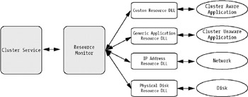
Microsoft Cluster Service in Windows Server 2003 is built on three key components:
Cluster service
Resource monitor
Resource DLLs
The cluster service is the core component as you can see in Figure 4-15, and runs as a high-priority system service.
The resource monitor is an interface between the cluster service and the cluster resources. This is run as an independent process. By using the resource API, the resource monitor and the resource DLLs communicate with each other. The API exposes a collection of entry points, callback functions and related structures, and macros to manage resources.
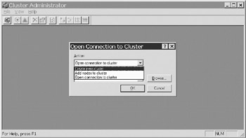
You have built-in tools to manage your clusters. The primary tool is the Cluster Administrator (see Figure 4-16). From this you can manage your cluster objects, perform maintenance, and monitor cluster activity.
The clusters you have seen so far all have one common denominator: The servers reside at the same place. What happens if the entire site disappears? Naturally you would lose all data, and your applications would vanish. This is perhaps a highly unlikely scenario, but the last few years of terrorist acts have taught us it could happen. A similar calamity does not have to be the result of something as dramatic as terrorism, either. Your office could catch fire and crumble to the ground. These are things you at least need to consider when designing a highly available application anyway.
| Note |
Keep one thing in mind though. You cannot protect yourself from everything. But you should strive for minimizing the possibility of everything going wrong at the same time. |
This reminds us of an experience we had at a Swedish company. Just to avoid embarrassing anyone, we won't mention any names. We were sent to a customer to help with an application. The company's server hall had two large steel safes in the middle of the room. When we asked we were told the company had duplicates of its most important servers in these safes. When one safe was opened, the room was not left unguarded. Someone was required to be there; otherwise the safe had to be closed. The administrator was, understandably, very proud of this solution, and we could bet someone could nuke the building and the servers would still be okay.
When we set to work on the application, we had to look through the event logs of one of the servers. We noticed a lot of warnings originating from the backup software. We asked if the company was aware of this and were told it was, and that the problem was going to be solved soon. But when we looked a little more thoroughly, we noticed that no backup of the servers existed at all. So even if the servers were protected in safes, no backup was available. If an error in the data sneaked in that would have to be corrected, this could not be fixed with a restore operation. Talk about a waste of money on the safe.
The point of this little anecdote is that you have got to plan carefully when you try to protect your data and applications. You do not want to make such a mistake yourself.
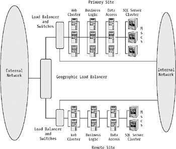
To avoid problems with a server hall vanishing, you could use multiple sites or separate parts of your clusters to different physical locations. The latter solution is called geographically dispersed clusters. Figure 4-17 shows an example of a multisite solution.
When you implement a multisite solution, you configure one location as the primary site, and the other (or others) as a remote site(s). The architecture at the remote site should mirror that of the primary. What components are mirrored, or any other considerations you might have, must be decided by your Service-Level Agreements (SLAs).
There are different ways to implement this kind of solution, and your choice depends on what level of security you need. When you have a full implementation design, you mirror everything at the remote site. This way the remote site can handle everything the primary site can. It can operate independently or, if necessary, handle the entire load. If you select this design, you need to set up real-time replication and synchronization of your databases and applications so you do not have sites that lack information. If you cannot set up real-time replication, you need to make sure you replicate as often as possible. You must then also be aware of the discrepancies that can occur in the data.
A partial implementation design is one that only mirrors specific components to the remote site(s). This solution obviously cannot cover for the primary site. What it can do is handle peak hours. It can also maintain limited uptime if the primary site fails. You could even use it to provide limited services as needed. If you choose a partial implementation, you need to consider how often you must replicate data. Is it necessary with real-time replication, or could you manage with less, and live with a certain latency?
To implement any of these two designs, you could use geographically dispersed clusters. This is a technique supported by MSCS. Instead of having a shared-nothing database on the same LAN, you must find a solution that works over long distances with this technique. This is most often done with the use of Virtual LANs (VLANs) that let you connect to SANs.
One of the improvements to geographically dispersed clusters (sometimes called stretched clusters) in Windows Server 2003 is the introduction of the majority node set. This is a new type of quorum resource, and it changes the way cluster quorum is used. This technique makes sure that cluster servers that are geographically dispersed still maintain consistency in case of a node failure.
Each cluster has a special resource called the quorum resource. A quorum resource usually does two things: The first is to provide a means for arbitration leading to membership and cluster state decisions. Second, it provides physical storage to store configuration information.
The following comes from "Server Clusters: Architecture Overview" by Microsoft Corporation, March 2003 (see http://www.microsoft.com/windowsserver2003/docs/ServerClustersArchitecture.doc for further information):
A quorum log is simply a configuration database for the server clustering. It holds cluster configuration information such as which servers are part of the cluster, what resources are installed in the cluster, and what state those resources are in (for example, online or offline).
There are two main reasons why the quorum is important in a cluster:
Consistency—Since the basic idea of a cluster is multiple physical servers acting as a single virtual server, it is critical that each of the physical servers has a consistent view of how the cluster is configured. The quorum acts as the definitive repository for all configuration information relating to the cluster. In the event of the Cluster Service being unable to read the quorum log, it will not start, since it is not able to guarantee that the cluster will be in a consistent state—one of the primary requirements for a cluster.
Tie-breaker—The quorum is used as the tie-breaker to avoid "split-brain" scenarios. A split-brain scenario happens when all of the network communication links between two or more cluster nodes fail. In these cases, the cluster may be split into two or more partitions that cannot communicate with each other. The quorum guarantees that any cluster resource is brought online on only one node. It does this by allowing the partition that "owns" the quorum to continue, while the other partitions are evicted from the cluster.
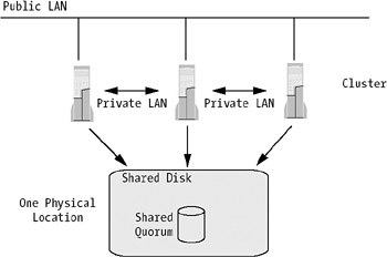
Figure 4-18 shows that an ordinary cluster configuration lets the quorum resource write information on all cluster database changes to a recovery log(s). This way you can recover cluster configuration and state data, if needed. The quorum resource is placed on a shared disk array. The information on the shared disks can be used to see if other nodes in the cluster are functioning.
Figure 4-19 shows a geographically dispersed cluster running Windows Server 2003.
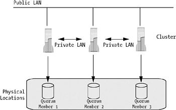
In this scenario, quorum data, including cluster configuration and state data, is stored on the system disk of each node in the cluster. This way a dispersed cluster can maintain a consistent state without the trouble of setting up quorum information on storage located on the interconnect.
In Windows Server 2003, MSCS is available in the Enterprise Edition and Datacenter Edition. Several changes have been made to MSCS in this new Windows version. Table 4-6 lists a few of these new features. Most noticeable is that MSCS is no longer an optional component. Now it is integrated into the operating system, enabling the servers to be configured as a cluster node, without access to installation media. Other benefits are that you can create and change clusters from a remote computer using cluster administration tools. You do not have to reboot your server after installation or change of the cluster configuration either.
|
Feature |
Description |
|---|---|
|
Larger clusters supported |
In Windows 2000, the Datacenter Edition allowed support for four-node clusters. Now you can support eight nodes using Windows Server 2003 Enterprise Edition or Datacenter Edition. This provides many more options for configuring your clusters. Take one of the examples shown in the "Server Clusters Using MSCS" section earlier and try for yourself. |
|
Better manageability |
The management tools have been polished and extended. Among these, Diskpart is a new tool that lets you expand cluster disks dynamically online. Applications can now be made cluster aware using scripting languages like VBScript and JScript. This way your developers (or administrators) can write add-ins for applications, thereby making them possible to monitor and control in a cluster. MSMQ support has been enhanced. It now includes support for triggers, allowing applications with high availability to be built and still have access to all the features of MSMQ. |
|
Active Directory integration |
Virtual servers can be registered in Active Directory. This means you now can use Kerberos authentication and delegation when your applications are run in a cluster. You do not have to know the exact location of the cluster either, but can instead look in the directory to find it. |
|
Quorum resource improvements |
As mentioned, beside the traditional cluster quorum mechanism, you now have the majority node set. As described previously, you can get great help from this in building your multisite, geographically dispersed clusters. |
|
EFS support |
Encrypting File System (EFS) is now supported on clustered disks. |
|
64-bit support |
Of course 64-bit support is included, and it lets applications take benefit of larger memory capacity. This will be pretty cool when the next version of SQL Server will be released. |
|
Storage capabilities |
Optimizations have been made in the support of Storage Area Networks. Worth mentioning here are targeted device resets and storage interconnect requirements. Distributed File Systems (DFS) has been improved. Now you find multiple stand-alone roots and independent root failover support for active/active configurations. You can now also support offline files on a clustered file share, meaning clients' cached data is stored on a clustered share. |
|
Various improvements or changes |
The cluster service account password can now be changed dynamically, without needing to take nodes offline. WMI support has been added to cluster control and management, cluster state change events, and application and cluster state information, just to mention a few changes. Log file handling and logs have been improved. There have also been improvements to the logic for a failover in the event a complete loss of internal communication within a cluster has occurred. |
Now you know more about the architecture of MSCS. Let us take a look at a few of the general requirements for clusters before examining some best practices.
To determine if your hardware is supported by the operating system, you can navigate to the Microsoft Web site and have a look at the Hardware Compatibility List (HCL). You can build your cluster on hardware not on the list, but then such a setup would not be a qualified configuration, and support from Microsoft would be limited.
Strive to use identical hardware whenever possible on the cluster servers. Use the same NICs, switches, and so on, to avoid problems.
When you plan your cluster, the object is to avoid a single point of failure. That is the whole idea of clustering, after all. To avoid problems with network connectivity, you should use two or more independent networks that connect the nodes of a cluster. You cannot allow these networks to have a common physical component, either. You must make sure they do not share switches and so on to avoid any single point of failure.
What else do you need to think about? When it comes to communication settings, there are a few important things to consider. The first thing would be to manually configure the NICs to use the same communication settings. You must also make sure the port settings on the switches match these settings.
| Tip |
Do not use automatic detection, as some NICs drop packages while negotiating the network settings. |
The subnets used for the cluster must have distinct subnet numbers that separate them from each other. For example, if you have two subnets, you could use the following addresses:
Subnet 1: 10.1.x.x mask 255.255.0.0
Subnet 2: 10.2.x.x mask 255.255.0.0
This way you have two separate subnets available. You could use DHCP on your subnets, but we strongly recommend manually configuring the IP addresses with static values; otherwise failure to renew a lease would disrupt cluster operations. To further avoid a single point of failure, you should use at least two of the subnets for internal cluster node communication. You can configure two settings here: One is Internal Cluster Communications only, and the other is All communications in Cluster Service. Of these, subnet 1 should be used exclusively for internal communication between cluster nodes. This is called the private network. Public networks, on the other hand, are those networks that clients use to communicate with the cluster.
All nodes participating in a cluster must belong to the same domain. To avoid a single point of failure, the domain also has to fulfill some requirements. The easiest way to do this is to duplicate everything. That is, use at least two domain controllers for a start. If you use DNS, you must make sure you have at least two DNS servers that support dynamic updates. All nodes in the cluster and all domain controllers must be configured with a primary and at least one secondary DNS server. Do not forget to have at least two global catalogs as well.
You also might want to address a few other issues:
Do not configure DNS, WINS, or default gateway servers on the private NICs. WINS and DNS servers should be configured on the public NICs, however.
If your public NICs are used for communication with clients or services on remote subnets, you should configure them with default gateways.
The private subnet should be isolated, so do not connect anything beside the cluster nodes. Do not implement any WINS, DNS, DHCP, or anything else on these subnets.
When you have geographically dispersed clusters, you should also think about the following:
You can let nodes in a cluster be on different physical networks. If you do, the private and public networks must appear as single, nonrouted LANs. You can accomplish this using techniques such as including VLANs. Remember to make sure all VLANs fail independently of all other networks if using this technique.
Latency for round-trip communication between cluster nodes must be less than 500 milliseconds. This value is also true for communication between the nodes and the SAN.
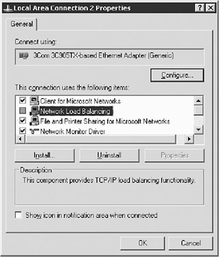
Network Load Balancing provides failover support for IP-based services and applications that need high scalability and availability as you saw in Chapter 3. An NLB cluster, like a MSCS cluster, exposes a virtual IP address that clients use to access the services of the cluster. The architecture of an NLB cluster is much simpler than that of a MSCS cluster, however. NLB runs as a network driver, as you can see in Figure 4-20. This means it does not require any special hardware to function.
What you need to consider is having IP networking installed on all load-balanced servers. This, of course, is due to the fact that Network Load Balancing is IP based.
You do not have to have common data storage configured as in MSCS either. All nodes in the cluster are equipped with the same information—for instance, exact copies of a Web site.
The normal scenario when setting up NLB is to use at least two NICs. One is set up as a cluster NIC and used to handle network traffic for the cluster. The other is set up as a dedicated adapter and handles traffic outside the cluster, like client-to-cluster communication.
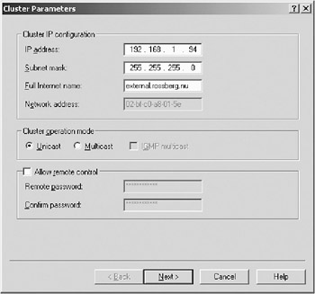
NLB can operate in two modes, as Figure 4-21 shows: unicast and multicast. The default mode is unicast to ensure it operates properly with all routers.
The NLB driver acts as a filter between the cluster adapter and the TCP/IP stack. This makes it possible to allow only traffic bound for the designated host to be received. Keep in mind that Network Load Balancing only controls IP traffic (TCP, UDP, and GRE) on special ports. You must therefore configure which port NLB should listen to. If NLB encounters traffic on a port not configured with NLB, it simply lets it pass through, without any modification to the IP stack.
One of the benefits of using Network Load Balancing to load balance your Web servers is that you do not have to rely on any specific hardware. The point is that you could take an off-the-shelf server and simply add it to your cluster without much hassle. You just add the data needed for your applications, like Web pages and other Web content, and you are ready to rock. You are not in any particular way dependent on any fault-tolerant hardware. You do not have to have any fancy RAID solution configured, because if the server fails, all its requests are rerouted to another server within ten seconds. You can then correct the error and add the server back to the cluster again. This cuts the hardware costs for an NLB cluster.
What you do have to spend some time and effort on is synchronizing data. No participating cluster server should contain old information. Luckily, there are tools that help you with this, so you do not have to update manually all 32 servers in your cluster. (For more information about content management, please see Chapter 5.)
Even though NLB is much simpler than MSCS, there is room for improvements in the Windows Server 2003 family. One thing that strikes us is that NLB is now supported on all the server members. The introduction of the Web Edition is a step in the right direction when it comes to building Web clusters. The cost of this edition is not much higher than the cost of Windows XP Professional, making it an excellent choice in these situations. Since one of the objectives with NLB is to keep costs down, and making it simple to implement is another, this is a good thing. You can now order a simple pizza-box server preconfigured with the Windows Server 2003 Web Edition, have it delivered to you, and quite easily add it to your cluster in practically no time at a cost of about $2000. There is no need for expensive Microsoft Web solutions any longer.
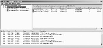
One of the problems with having a large NLB cluster involves administering all the servers. Tools like Application Center have made life easier in the past, but now quite capable management applications are coming out of the box. One of these tools is the Network Load Balancing Manager (see Figure 4-22). With this tool, you can create new NLB clusters and configure existing ones. You can also use it to add and remove cluster members.
Another benefit with the Network Load Balancing Manager is that you can use it to diagnose improperly configured clusters easily.
You can use this tool not only for the clusters on the server Network Load Balancing Manager is run from, but also for remote administration of other NLB clusters. This way you have a single point of configuration and management for your NLB clusters.
Another feature of NLB in Windows Server 2003 is the introduction of virtual clusters. This feature can be used to configure different port rules for different cluster IP addresses. In this case, each IP address corresponds to a Web site or application hosted on the NLB cluster. You can also use it to select which host in a cluster should be used to service traffic sent to a specific Web site or application on the cluster.
In Windows Server 2003 you have the possibility of binding NLB to multiple NICs. By doing so, you can host multiple clusters on the same hosts, despite the fact that they are on independent subnets. This also lets you use NLB for firewall and proxy load balancing in those cases where you need load balancing on multiple fronts of a proxy or firewall.
When NLB is running in multicast mode, you can enable Internet Group Management Protocol (IGMP) support on it. This allows you to limit switch flooding to only those ports on a switch that have NLB machines connected to them. This is done to conserve network resources.
| Note |
Switch flooding is caused by the NLB algorithm. This algorithm requires all hosts in an NLB cluster to see every incoming packet addressed to the cluster. |
Now we will introduce you to what we consider some of the best practices for NLB based on our experience over the years.
When you operate your clusters in unicast mode, NLB cannot distinguish between single NICs on the hosts. This is why you need a separate NIC for internal cluster communication.
You should only configure TCP/IP on a NIC where NLB is enabled.
In order for you to more easily manage troubleshooting, you should enable NLB logging. In Figure 4-23, you can see where this should be enabled in the Network Load Balancing Manager. When you do this, you need to specify a log file, since this logging does not use the Event Viewer.
Make sure that all cluster parameters and port rules are set identically on all cluster nodes. Check so that all ports used by NLB have port rules set. That means you should make sure FTP traffic is directed to port 20 and 21 or any other port of your liking. After a port rule is set, always click Add; otherwise the rule will not take effect.
Since NLB does not stop and start applications, you must make sure they are started on all cluster hosts on which they are installed. You need to ensure the applications are started so your cluster gives you the best benefits.
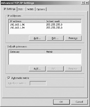
One thing that might seem obvious is nevertheless worth mentioning. Make sure that the same IP addresses are entered in the TCP/IP properties as in the NLB setup. Also make sure that the dedicated IP address is listed before the cluster IP address in the TCP/IP properties box (see Figure 4-24). Otherwise, you cannot ensure that responses to connections originating from one host will return to the same host. (In our case, 192.168.1.96 is the dedicated IP address, and 192.168.1.94 is the cluster IP address, as you can see in Figure 4-24.)
| Caution |
Keep in mind that you should configure both the cluster IP address and the dedicated IP addresses as static. Do not use DHCP here, the same way you would not use it for MSCS. |
The hosts in a cluster should belong to the same subnet. All clients must then have access to this subnet, unless, of course, you do want the cluster to be idle. (But then you would not have set up a cluster in the first place.)
You cannot enable NLB on a server that is part of a MSCS cluster. Or rather you could, but Microsoft does not support it. We have not tried it, however, and really cannot say what the result would be.
When you configure your NICs for load balancing, you should configure a default gateway for the NLB NIC in case you have two (or more) NICs on different subnets. You should also update your routing tables so that all traffic will go through this gateway. The gateway settings on the other NICs should be blank. If your NICs are on the same subnet, you do not need to hack the routing tables. (Remember that this last point only applies to Windows 2000 systems and not to Windows Server 2003 systems.)
If you do not want to use the graphical management tools for NLB, you could use the command-line–based nlb.exe, which lets you configure NLB through the command line.
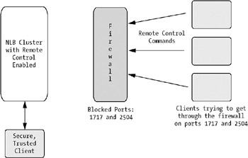
While we are talking about management tools, it might be worth mentioning that you can control your clusters remotely. You choose during setup if you want to allow this, but based on our experience we do not recommend this. Using the remote control option presents too many security risks. Some of the risks are more exposure to data tampering and denial of service attacks if you allow this, so use the Network Load Balancing Manager or WMI instead.
If you do want to enable this option for some reason, you must make sure you provide a strong password. You should also protect the NLB cluster with a firewall and block the UDP control ports necessary for remote control. (The default values for these ports are 1717 and 2504 at the cluster IP addresses.) Only access the cluster with remote control from a secure, trusted computer behind a firewall, as Figure 4-25 shows.
| Caution |
Please do not use the remote control option unless absolutely necessary. |
Finally, we will show you some ways to troubleshoot NLB. There are various tools to help you with this. An old favorite is, of course, the Event Viewer. Check this to see if any unexpected errors have occurred.
The ping command is useful for checking if the cluster is alive and responds to requests.
Do not forget to enable NLB Manager logging as shown previously. The logs can be useful in troubleshooting.
You also might want to keep an eye on a few performance monitors:
CPU load
Network interface: packets/sec
Web service: connection attempts/sec
The nlb.exe command-line tool also has a few commands that might come in handy. Check out the Display and Query commands to find out whether you might prefer to work with this tool. You can also find more information at http://www.microsoft.com/windowsxp/home/using/productdoc/en/default.asp?url=/windowsxp/home/using/productdoc/en/nlb_command.asp or by just typing nlb /? at the command prompt.