


A Deployment diagram shows how and where the system is to be deployed. Physical machines and processors are reflected as Nodes, and the internal construction can be depicted by embedding Nodes or Artifacts. As Artifacts are allocated to Nodes to model the system's deployment, the allocation is guided by the use of deployment specifications.
Example Diagram
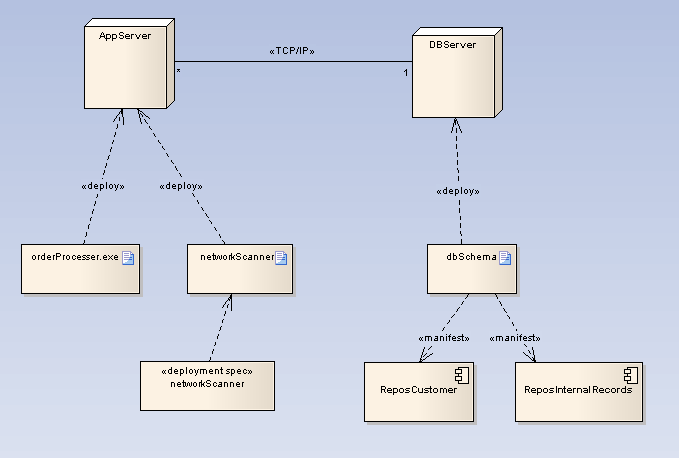
An example Deployment diagram is shown below. The two Nodes have a TCP/IP communication path indicated. Deployment relationships indicate the deployment of Artifacts. Furthermore, a deployment spec defines the process of deployment for the networkScanner Artifact. The Manifestation relationships reveal the physical implementation of components ReposCustomer and ReposInternalRecords.
Toolbox Elements and Connectors
Select Deployment diagram elements and connectors from the Deployment pages of the Enterprise Architect UML Toolbox.
Tip: Click on the elements and connectors below for more information.
Deployment Diagram Elements |
Deployment Diagram Connectors |
|
|
|
|
|
|
|
|
|
|
|
|
|
|
|
|
|
|
OMG UML Specification
The OMG UML specification (UML 2.0 Superstructure, p. 8) states:
"A diagram that depicts the execution architecture of systems. It represents system artifacts as nodes, which are connected through communication paths to create network systems of arbitrary complexity. Nodes are typically defined in a nested manner, and represent either hardware devices or software execution environments."