


There are two nodes used to define a final state in an Activity, both defined in UML 2.0 as of type Final Node. The Flow Final element depicts an exit from the system, as opposed to the Activity Final, which represents the completion of the Activity. Only the flow entering the Flow Final node exits the Activity; other flows continue undisturbed.
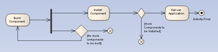
The following example Activity Diagram illustrates the development of an application. The process comes to a Flow Final node when there are no more components to be built; note that the Fork element indicates a concurrent process with the building of new components and installation of completed components. The Flow Final terminates only the sub-process building components. Similarly, only those tokens entering the decision branch for the installation of further components terminate with the connecting Flow Final (that is, stop installing this component, but keep on installing other components). It is only after the Deliver Application activity is completed, after the control flow reaches the Final node, that all flows stop.
See UML Superstructure Specification, v2.0, figure 251, p. 332.
Toolbox Icon
![]()
OMG UML Specification
The OMG UML specification (UML Superstructure Specification, v2.0, p. 333) states:
"A flow final destroys all tokens that arrive at it. It has no effect on other flows in the activity."