


|
|


See UML Superstructure Specification, v2.0, figure 255, p. 335.
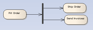
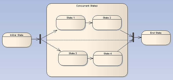
These elements are used in both Activity and State Machine diagrams. With respect to State Machine diagrams, a Fork pseudo-state signifies that its incoming transition comes from a single state, and it has multiple outgoing transitions. These transitions must occur concurrently, requiring the use of concurrent regions, as depicted below in the Composite State. Unlike Choice or Junction pseudo-states, Forks must not have triggers or guards. The following diagram demonstrates a Fork pseudo-state dividing into two concurrent regions, which then return to the End State via the Join pseudo-state
OMG UML Specification
The OMG UML specification (UML Superstructure Specification, v2.0, p. 471) states:
"Fork vertices serve to split an incoming transition into two or more transitions terminating on orthogonal target vertices (i.e. vertices in different regions of a composite state). The segments outgoing from a fork vertex must not have guards or triggers."