


Note: State Machine diagrams were formerly known as State diagrams.
A State Machine diagram illustrates how an element (often a Class) can move between states, classifying its behavior according to transition triggers and constraining guards. Other aspects of State Machine diagrams further depict and explain movement and behavior. State Machine representations in UML are based on the Harel State Chart Notation (see the OMG UML Superstructure Specification 2.1.1, section 15, State Machines), and therefore are sometimes referred to as State Charts.
You can display a State Machine as a diagram (as below) or as a table in one of three relationship formats. In all formats, you use the same Enterprise Architect UML Toolbox elements and connectors.
To select the display format, follow the steps below:
| 1. | Right-click on the diagram background to display the context menu. |
| 2. | Select the Statechart Editor option. |
| 3. | Select the appropriate display option: |
| · | Diagram |
| · | Table (State-Next State) |
| · | Table (State-Trigger) |
| · | Table (Trigger-State) |
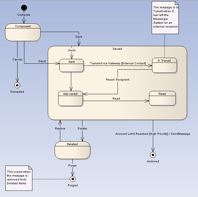
Example Diagram
The diagram below illustrates some features of State Machine diagrams. The Saved state is a Composite State, and enclosed states are sub-states. Initial and final pseudo-states indicate the entry to and exit from the State Machine. Composite States and sub-states are both State elements, a Composite State being an expanded State element that encloses other State elements, which are then referred to as sub-states.
Toolbox Elements and Connectors
Select State Machine diagram elements and connectors from the State pages of the Enterprise Architect UML Toolbox.
Tip: Click on the elements and connectors below for more information.
State Machine Diagram Elements |
State Machine Diagram Connectors |
|
|
|
|
|
|
|
|
|
|
|
|
|
|
|
|
|
|
|
|
|
|
|
|
See Also
OMG UML Specification
The OMG UML specification (UML Superstructure Specification, v2.1.1, Section 15.3.12 ) states:
"A state machine owns one or more regions, which in turn own vertices and transitions.
"The behaviored classifier context owning a state machine defines which signal and call triggers are defined for the state machine, and which attributes and operations are available in activities of the state machine. Signal triggers and call triggers for the state machine are defined according to the receptions and operations of this classifier.
As a kind of behavior, a state machine may have an associated behavioral feature (specification) and be the method of this behavioral feature. In this case the state machine specifies the behavior of this behavioral feature. The parameters of the state machine in this case match the parameters of the behavioral feature and provide the means for accessing (within the state machine) the behavioral feature parameters.
A state machine without a context classifier may use triggers that are independent of receptions or operations of a classifier, i.e. either just signal triggers or call triggers based upon operation template parameters of the (parameterized) state machine."