A State Machine table is one of two variants of a State Machine (the other is the State Machine diagram). It displays the information of the State Machine in table form, and is a method of specifying the discrete behavior of a finite state-transition system; that is, what state the State Machine moves to and the conditions under which the transition takes place.
You can display the state transition as one of two different relationships:
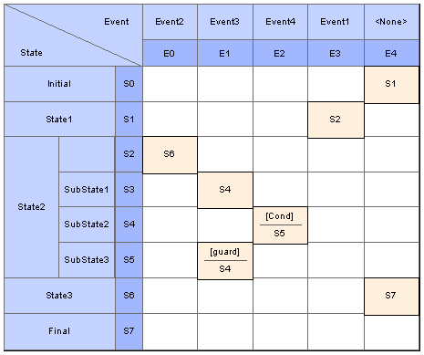
| · | State - Trigger: The rows indicate the current states and the columns indicate trigger events (or the other way around if you prefer, in a Trigger - State format). The cell at the intersection of a row and column identifies the target state in the transition if the trigger occurs, and the condition (or guard) of the transition. |
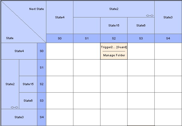
| · | State - Next State: The rows and columns both indicate states, and the cell at the intersection of a row and column indicates the event that triggers a transition from the current (row) state to the next (column) state, the condition (or guard) of the event, and the effect of the transition. |
Select Format
You can display a State Machine as a diagram or table, and as a table in one of three relationship formats.
To select the display format, follow the steps below:
| 1. | Right-click on the diagram background to display the context menu. |
| 3. | Select the appropriate display option: |
See Also


