After requirements definition, Angela, one of the data analysts on the team, ap proached Mike, the system's architect, and reasserted her previous concerns about the business object model for Manage Clinical Records. (Mike understood that such an apparent 揵ack step?is not uncommon during an object-oriented development process and indeed is usually very valuable. Problems avoided increase quality and speed development. He also understood that this would be a hard sell to project management.) As you recall, during business modeling, Angela expressed concern about how the Clinical Records were being modeled (see Figure 3-18). The use of New, Old, and External in the Clinical Records entity names seemed to be trying to capture the 搒tate?of these entities or possibly trying to capture time-variant behavior of the various Clinical Records entities. The understanding that she developed while working through requirements definition only increased her concern. After reviewing it together Mike agreed, and they set about to remodel that business object model.
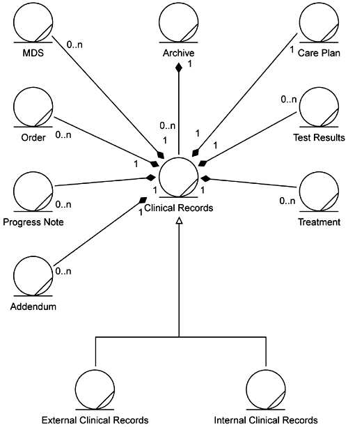
Their first rework is shown in Figures 5-1 and 5-2. They simplified the model by splitting it into two diagrams. The first, Figure 5-1, captures just the relationships of other elements to the Clinical Records (CR). The second, Figure 5-2, captures the relationships among the types of Clinical Records. It is here where Angela's concerns lie.
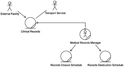
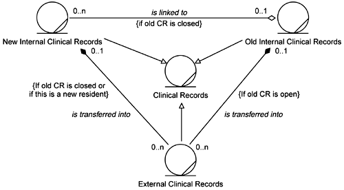
They felt that Figure 5-2 more clearly expressed the relationships among the types of Clinical Records. However, there still seemed to be some implicit time or state behavior in these relationships. So they went back to the business people and asked if this model properly described the situation. The business folks verified that the model did correctly describe the handling of External Clinical Records. (External Clinical Records simply become part of the Old Clinical Records if the Old Clinical Records are open. If the Old Clinical Records are closed, the External Clinical Records are put into a New Clinical Record that is linked to the old, closed ones.) However, they also revealed that in the business they do not really have New Clinical Records. The business people think of them as only Internal Clinical Records and External Clinical Records. This led the development team to the model shown in Figure 5-3.
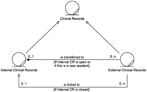
While simpler, this model still has the same shortcomings of the previous models; the state of the files is bound up in the constraints on the relationships. The team also realizes that these depictions focus on what to do with the External Clinical Records only. What about the possibility of linking multiple sets of Internal Clinical Records? Is that a valid situation?
Angela suggested that they try modeling the Clinical Records with the concept of 搒tate?(that is, open records, closed records, and so on) separate from the rest of the model. The team members also decided to test what they model with some scenarios to see if the modeled structure can support various operational flows. For example, one Resident, for whatever medical reasons, goes to and from the Facility as follows:
Resident arrives without any External Clinical Records.
Resident leaves the Facility.
Resident returns after one month without any External Clinical Records.
Resident leaves the Facility.
Resident returns after seven days with External Clinical Records.
Test results (that is, External Clinical Records) for this Resident return to the facility five days later.
Resident leaves the Facility.
Resident returns two months later with External Clinical Records.
Resident leaves the Facility.
Resident returns six months later with no External Clinical Records.
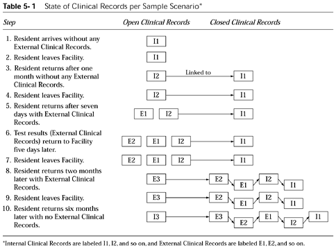
What did the team learn from this scenario? The Clinical Records situation for this scenario is shown graphically, stepping through the above flow, in Table 5-1. This table shows when clinical records are created, the state (open, closed) of the various clinical records, how they move from open to closed over time, and how they would be linked in the above scenario.
Two interesting items learned from this exercise are that:
The open clinical records can actually contain more than one set of External Clinical Records (step 6).
Newly created Internal Clinical Records may also need to be linked to closed Clinical Records (not just new External Clinical Records) (step 10).
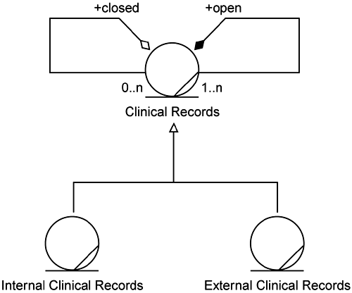
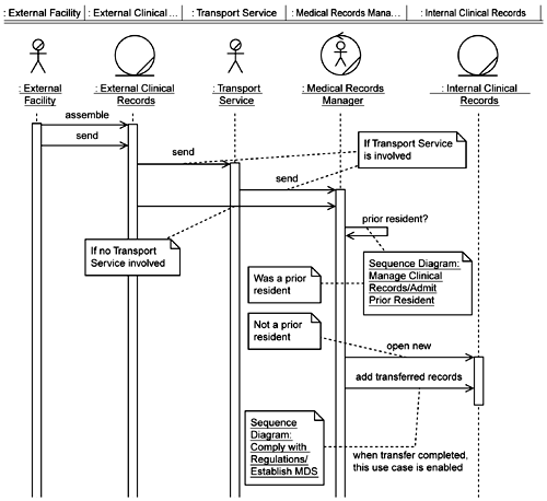
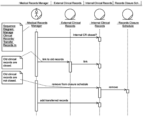
Putting all this together, the team created a new model for the relationships among Clinical Records (Figure 5-4). This shows, as we were told by the business people, that there are two types of Clinical Records桰nternal and External. Closed Clinical Records may be linked to other Clinical Records (Internal or External). Open Clinical Records contain other Clinical Records (Internal or External). The team then used these changes to update the other relevant models (Figures 5-5, 5-6, and 5-7).
The development team now moves forward to first address the part of OMaR that deals with compliance with government regulations. This direction was chosen for two primary reasons: (1) EAB Healthcare must remain in compliance or the business risks being shut down, and (2) one of the most critical sections of the Clinical Records, the MDS, is central to EAB's operation. Each MDS contains data that provide a complete look at the condition of each resident. It is the one entity that is used most by the nursing staff, is used to create other important data entities, and is required to be updated and accurate to remain in compliance with regulations. The MDS is central to both the clinical and managerial operations of EAB Healthcare. Failure here would be disastrous. Therefore, the development team addresses this high-risk area first.
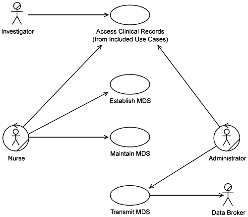
You will recall that within the Comply with Regulations subsystem three of its use cases were selected as high priority: Establish MDS, Maintain MDS, and Transmit MDS (Figure 5-8).
The team proceeds to develop the sequence diagrams and class models for these use cases, beginning with Establish MDS. This use case is used to create the MDSs. They decide to prepopulate the class diagram by building the Nurse's view of this use case (the Nurse is the only actor using Establish MDS). They populate this view with entities with which the Nurse interacts when establishing the MDS (Figure 5-9). Such information can be found in the use case specification for Establish MDS.
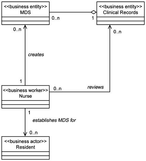
Note that these entities are shown in the form of the typical class stereotype. Using this information the development team can now build the sequence diagram for the Establish MDS use case. The team members start by looking at the sequence diagram for the business use case Establish MDS. (By using sequence diagrams instead of activity diagrams in the business object model, we can use the business-level sequence diagram to prepopulate the sequence diagram for the system use case Establish MDS.) Starting here they elaborate the Establish MDS system use case guided by the information in the use case description developed during requirements definition.
In addition to adjusting the basic message flow in the sequence diagrams, the team also adds additional processing regarding the linkage of current MDSs with prior MDSs. The knowledge that all MDSs for the same resident must be linked together was revealed during business modeling as part of the work on the Managing Clinical Records use case. Thus the team leaves the MDS linking function in the Manage Clinical Records / Admit Prior Resident sequence diagram (see Figure 5-6). That functionality is not required when creating new MDSs for new Residents (see Figure 5-10).
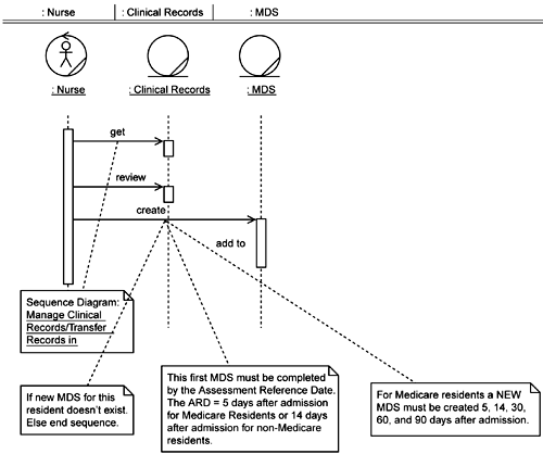
Also during business modeling the need for MDSs to be created and up dated on certain timelines was established (see annotations on Figure 5-10). At that time the team members did not specify how this was to be accomplished (rightly so since in the business modeling and requirements definition phases they were establishing what was to be done, not how). This processing is not included on this sequence diagram since it is not truly part of establishing an MDS, but establishing an MDS does trigger this processing. The team makes a preliminary design decision that this processing will run at night and report on MDSs that have not been updated according to the required timeline. (Note that they have not specified, at this time, the specific technology梑ackground process, stored procedure, and so on梩hat will be used to do this.) The team documents this by updating the use case specification and by adding this into the class diagram (Figure 5-11) via a new control class, MDS Monitor. The team also creates a statechart diagram for the MDS Monitor class (Figure 5-12). This diagram specifies the locking and processing of the MDSs, including all the conditions upon which the MDSs will be logged as being in violation.
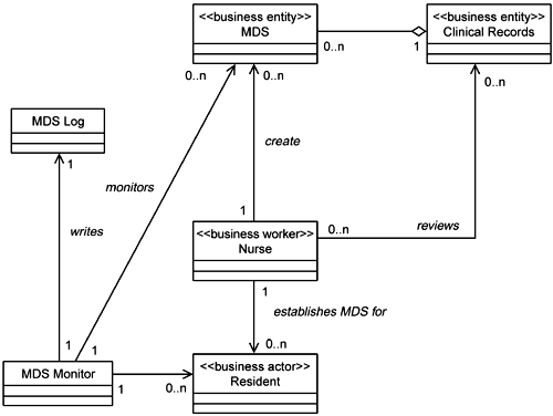
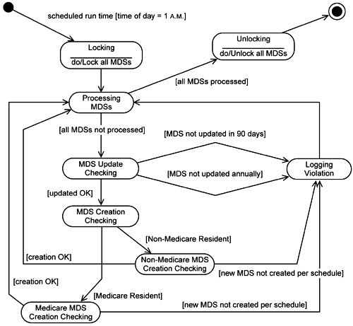
The new MDS log simply is a report generated listing the MDSs that are out of compliance regarding the timelines for creating and updating them. The MDS Monitor class is a control class that is responsible for monitoring the timelines and reporting the violations.
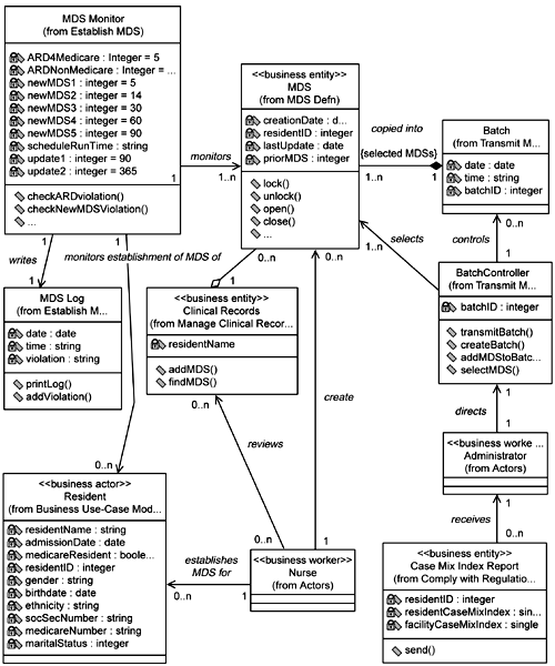
From this point the team members begin to elaborate further details of the class diagram using all the information at hand and their development experience. For the purposes of Establish MDS, the Resident class merely holds basic identifying information about the Resident (obtained from supplementary specifications and discussions with the nursing staff). Little is done with the Clinical Records other than searching them for a specific resident or to add a new MDS (all from the sequence diagram). For the MDS class, typical basic operations are added beyond what was specified. Yet this is not a full definition of the MDS, only that which is needed for Establish MDS. The timeline parameters (that is, the business rules) for the creation and updating of the MDSs are added in the MDS Monitor class. Basic log information is added to the MDS Log. The Nurse class has little elaboration here since its only real interaction, other than requesting and providing clinical information, likely lies with the Access Clinical Records use case. This will be elaborated upon when that use case is ad dressed. The resulting preliminary design class diagram is shown in Figure 5-13.
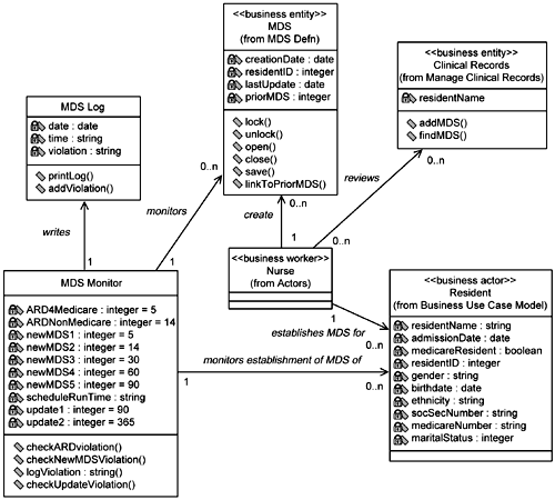
Database DesignerIf you hadn't noticed, the MDS Monitor class is capturing key business rules for the system. As noted in the text, how the enforcement of these rules is to be accomplished has not been established yet. But having these rules modeled visually (instead of buried in a specification or hidden behind a model) allows you to immediately see that this is an area you may want to address. It depends on which side of the business rules argument you fall. If you want to enforce these rules in the database, the inclusion of this class in the model has put you on notice that it needs to be addressed. You should begin to do your analysis to determine where it would be best implemented梚n the database, in the application, or within a separate business layer. |
The team now proceeds in a similar fashion with the Maintain MDS system use case. The previously developed business use case description for Maintain MDS was left at a suspiciously high level of detail (see Appendix B). The team updates the sequence diagram (Figure 5-14) to add in the locking, unlocking, and updating insights that arose as they developed the Establish MDS class diagram.
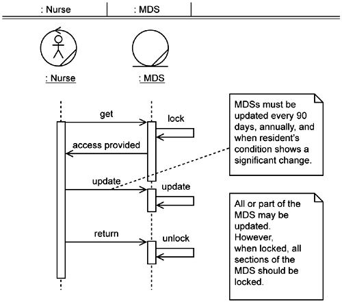
This use case is very simple in that its purpose is to merely allow access to the MDS for updates by the Nurse. Given that, the team decides that the design as expressed in the Establish MDS use case provides such access and there is no need for an additional class model for Maintain MDS.
However, this sounds too simple to the team leader. She questions what it means to 搈aintain the MDS.?The team members know from discussions with the business people and a quick look at some supplementary specifications on the MDS that it contains much information. Does the Nurse update the entire MDS or is it a partial update? If it is partial, can multiple Nurses update different sections of the MDS? Can they do this at the same time? Can any MDS be up dated or only the newest one? The team leader decides that it's time to look closer at the MDS and assigns one of the analysts to build a UML model of the MDS, using the supplemental specs, so they can all see what they have.
She was correct. It was too simple. Even after reading the supplemental information, it was not apparent until they went back to the nursing staff that there is not just one type of MDS; there are many. Each is used for a different purpose and they coexist. Whether a Resident's records contain one or many types of MDSs, all the Resident's MDSs are referred to collectively as the Minimum Data Set. This lead to the initial class model of the MDS shown in Figure 5-15.
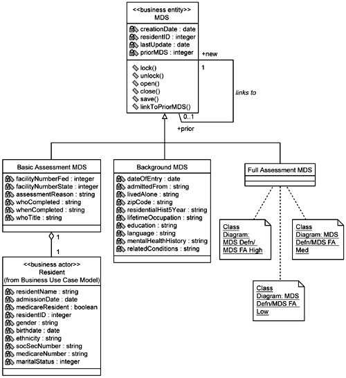
There is the Basic Assessment MDS that primarily provides identifying in formation. Thus you can see that the Resident class is part of the Basic Assessment MDS, as expressed by the aggregation. There is a Background MDS, which is typically created only once and contains some basic background information on the Resident. The Full Assessment MDS contains the bulk of the information, so much so that the team members decide to divide the Full Assessment MDS into three additional models. Thinking ahead to performance concerns, they use the criterion of the relative rate at which the individual sections of the MDS are updated: high, medium, or low (Figures 5-16, 5-17, and 5-18, respectively). The individual classes that represent the different sections of the MDS are then populated with attributes taken directly from the supplemental specifications. Each of these sections is relatively cohesive, representing one aspect of the Resident's condition (for example, Mood class, Medication class). For this primary reason the analyst chooses to represent each section as an individual class (versus one huge MDS class with everything in it). Note that this is not necessarily the way the MDS will be structured in the final data model. This is a representation of how it is composed in the current supplemental specifications provided by the business people.
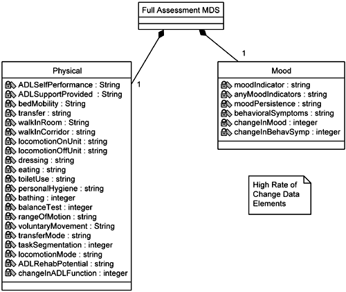
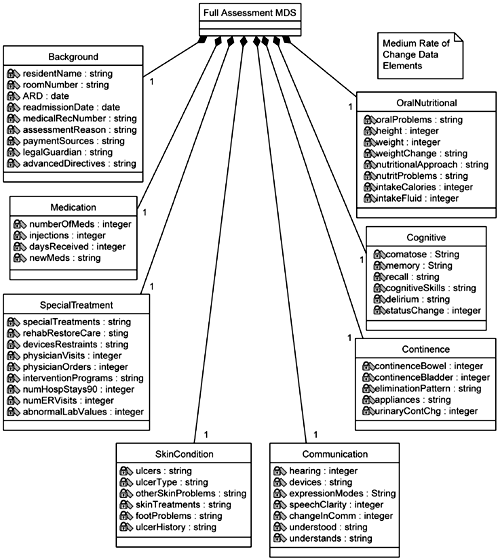
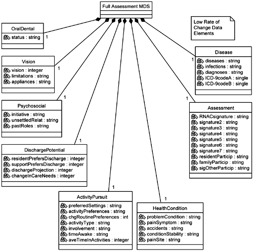
Other information is gleaned from the business people during this uncovering of the MDS that answers the team leader's questions. Any given MDS update may be partial. The only items in the MDS that cannot be updated by the Nurse are the signatures and dates of the other staff personnel who have signed and dated the MDS. Only one Nurse can update an MDS at a time. Only the newest MDS can be updated (prior ones that have already been transmitted to the government are locked against update).
The Transmit MDS system use case is for sending the updated MDS to the overseeing government agency for its review and approval. The team again updates the existing sequence diagram for this use case (Figure 5-19). Aside from some minor message flow changes, the team adds the concept of a 揵atch?of MDSs that are sent together as a group for approval.
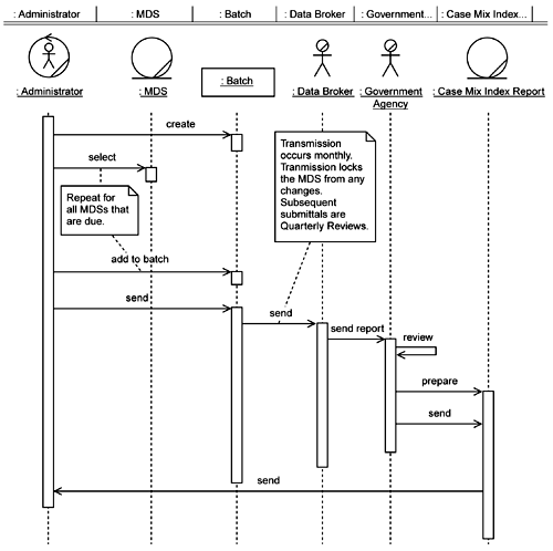
Since all the dynamic behavior in this use case consists of operational activities (that is, activities performed by the facilities staff), the Administrator's view, created by the development team, becomes the class diagram for Transmit MDS (Figure 5-20).
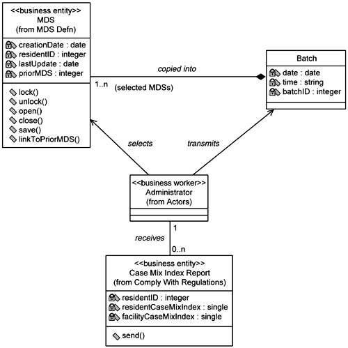
As stated in the use case specification for the Transmit MDS system use case, and as seen in this class diagram, it is the Administrator who selects the MDSs to include in the batch to be transmitted.
Database DesignerAt this point, the database designer raises a red flag. While the Batch class may be a good object-oriented representation of the set of MDSs being transmitted, there may be a better way. Recalling how critical this whole process is to the survival of EAB Healthcare and recalling the EAB staff mentioning how the transmission of the MDS sometimes fails (for reasons beyond EAB's control), the database designer suggests that Batch not be a fully transient class. He suggests that Batch be split into two classes: one persistent class, which will contain all the MDSs in the batch, and one transient class that handles the dynamic behavior of creating and transmitting the batch. Thus the Transmit MDS class model is modified as shown in Figure 5-21. Figure 5-21. Updated class diagram for the Transmit MDS system use case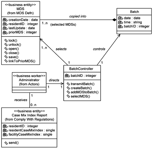 |
The team decides to create an integrated view of the class models to ensure that nothing unusual was created, design-wise, between the individual class diagrams. The integrated class model is shown in Figure 5-22.
