The following UML, object-oriented, and other concepts are cited in this chapter. For a more complete discussion and more rigorous definitions of UML concepts, refer to Booch et al. [1999].
Component?/B>? a physical and replaceable part of a system that conforms to and provides the realization of a set of interfaces
Dependency?/b>? a relationship between two elements in which a change to one element may affect the semantics of the other
Deployment diagram?/B>? a diagram depicting the hardware configuration used for the database and applications
Device?/b>? a node that has no processing capability
Processor?/b>? a node that has processing capability
Connection?/b>? the association used to show relationships among devices, processors, and each other
The implementation of the database is accomplished through the development of artifacts that are generated to the database or through script files. To model these artifacts in the UML, components are used. A component is a unit that serves as a building block for the physical structure of the system. The component in database terms serves as a unit that is used for code generation. The components used in database design are tablespaces, databases, and schemas. Components have relationships with other components and with other elements, for example, tables. The relationship used to associate with a component is a dependency. When a dependency exists, for example, between a table and a tablespace, the tablespace's existence depends on the tables involved in the relationship.
Using the UML for database design allows the modelers to model not just database structures but also the deployment or hardware for the system. A deployment diagram has elements available to model such things as the server and its drives. There are two types of elements involved in the deployment diagram: (1) a device, which is a piece of hardware without any computing power, like a drive, and (2) a processor, which is a piece of hardware that can do computation or can be the server itself. Relationships between deployment elements are created using a connection type of relationship.
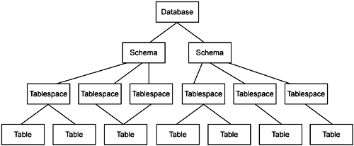
Many concepts that are not covered in the UML specifications and books are covered in this chapter as we examine storage modeling from the UML Profile for Database Design. The Profile adds stereotypes and tagged values that are attached to the stereotypes but does not change the underlying metamodel for the UML. This second part of the Profile concentrates on the components and deployment ability of the UML. The structure of the database storage can been seen in Figure 8-2.

As stated many times previously in this book, using the UML to design databases means more than just modeling the database structures of tables, col umns, and relationships梚t means modeling the entire database design from requirements to deployment. The section of the UML Profile for Database De sign that is relevant to this stage of the case study concentrates on the ability to model how and where the data is stored. No matter how many database designers and database administrators we have talked to, when we discuss how to design the storage of the data it always seems to be a difficult subject. The subject of data storage is difficult not because of the technology but because it is hard to understand where everything lies and to ensure that each piece of data is stored in the correct and most economical place. When discussing the UML for database design and its ability to model how the data is stored, we have seen the eyes of database team members just light up. Some of the comments we have heard include
揟his will help me to ensure that I have a storage unit for all data.?/p>
揘ow I can see if tablespaces are overused or need to be expanded.?/p>
揑t is difficult when partitioning tables to quickly know what data exists where, and modeling would sure help.?/p>
We have drawn diagrams all over the world on data storage, and designers in the audience always react the same way: they wish they had this ability in the past and they can't wait to try it. They know it is time consuming to try to understand how to structure the data. Being able to visualize it makes the job much easier.
Using the UML diagram elements available for modeling components gives database designers the ability to model the majority of the storage. Modeling the storage uses
Components
Devices
Dependencies
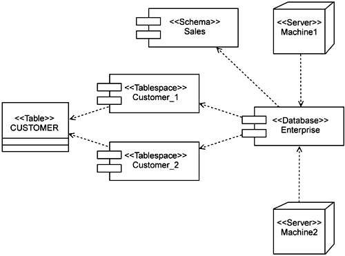
A component is stereotyped as either <<Tablespace>> or <<Database>> and it assumes additional tagged values based on each. A component is also stereotyped as <<Schema>> and represents the schemas within the database. A device represents a <<Server>> and a dependency is used to draw relationships among the tablespaces, databases, and servers. A dependency is also used to draw a relationship between tables and their assigned tablespaces (Figure 8-3).

There are several attributes that appear on a tablespace as well to capture storage information. A tablespace can be partitioned across several drives and therefore has attributes associated to drives. There can be one or more drives per tablespace. The tablespace also has multiple physical storage volumetric parameters. These parameters are calculations on the size of the tablespace and are captured as tagged values upon the tablespace and often on each individual table. The properties for each tablespace vary greatly depending on the DBMS chosen and even across versions of the same vendor's system. In the Profile, we cover a very generic construct for the tablespace properties, but the UML is extensible, as shown in this chapter, and you can add additional tagged values as needed to accomplish all the modeling needs of your particular DBMS.