Employee Number (E#)
Name
Occupation
Degree (Highest Degree Obtained)
Sex
Location
Marital Status (MS)
Salary
Sample data for such a file is provided in figure 10.1.
Record E# Name Occupation Degree Sex Location MS Salary
-----------------------------------------------------------------------
A 800 HAWKINS programmer B.S. M Los Angeles S 10,000
B 510 WILLIAMS analyst B.S. F Los Angeles M 15,000
C 950 FRAWLEY analyst M.S. F Minneapolis S 12,000
D 750 AUSTIN programmer B.S. F Los Angeles S 12,000
E 620 MESSER programmer B.S. M Minneapolis M 9,000
Figure 10.1 Sample Data for Employee File
The primary objective of file organization is to provide a means for record retrieval and update. The update of a record could involve its deletion, changes in some of its fields or the insertion of an entirely new record. Certain fields in the record are designated as key fields. Records may be retrieved by specifying values for some or all of these keys. A combination of key values specified for retrieval will be termed a query. Let us assume that in the employee file of figure 10.1. the fields Employee Number, Occupation, Sex and Salary have been designated as key fields. Then, some of the valid queries to the file are:
Retrieve the records of all employees with
Q1: Sex = M
Q2: Salary > 9,000
Q3: Salary > average salary of all employees
Q4: (Sex = M and Occupation = Programmer) or (Employee Number > 700 and Sex = F)
One invalid query to the file would be to specify location = Los Angeles, as the location field was not designated as a key field. While it might appear that the functions one wishes to perform on a file are the same as those performed on a symbol table (chapter 9), several complications are introduced by the fact that the files we are considering in this chapter are too large to be held in internal memory. The tables of chapter 9 were small enough that all processing could be carried out without accessing external storage devices such as disks and tapes.
In this chapter we are concerned with obtaining data representations for files on external storage devices so that required functions (e.g. retrieval, update) may be carried out efficiently. The particular organization most suitable for any application will depend upon such factors as the kind of external storage device available, type of queries allowed, number of keys, mode of retrieval and mode of update. Let us elaborate on these factors.
We shall be concerned primarily with direct access storage devices, (DASD) as exemplified by disks. Some discussion of tape files will also be made.
The examples Q1 - Q4 above typify the kinds of queries one may wish to make. The four query types are:
Q1: Simple Query: The value of a single key is specified.
Q2: Range Query: A range of values for a single key is specified
Q3: Functional Query: Some function of key values in the file is specified (e.g. average or median)
Q4: Boolean Query: A boolean combination of Q1 - Q3 using logical operators and, or, not.
The chief distinction here will be between files having only one key and files with more than one key.
The mode of retrieval may be either real time or batched. In real time retrieval the response time for any query should be minimal (say a few seconds from the time the query is made). In a bank the accounts file has a mode of retrieval which is real time since requests to determine a balance must be satisfied quickly. Similarly, in an airline reservation system we must be able to determine the status of a flight (i.e. number of seats vacant) in a matter of a few seconds. In the batched mode of retrieval, the response time is not very significant. Requests for retrieval are batched together on a "transaction file" until either enough requests have been received or a suitable amount of time has passed. Then all queries on the transaction file are processed.
The mode of update may, again, be either real time or batched. Real time update is needed, for example, in a reservation system. As soon as a seat on a flight is reserved, the file must be changed to indicate the new status. Batched update would be suitable in a bank account system where all deposits and withdrawals made on a particular day could be collected on a transaction file and the updates made at the end of the day. In the case of batched update one may consider two files: the Master File and the Transactions File. The Master File represents the file status after the previous update run. The transaction file holds all update requests that haven't yet been reflected in the master file. Thus, in the case of batched update, the master file is always 'out of date' to the extent that update requests have been batched on the transaction file. In the case of a bank file using real time retrieval and batched update, this would mean that only account balances at the end of the previous business day could be determined, since today's deposits and withdrawals haven't yet been incorporated into the master file.
The simplest situation is one in which there is only one key, the only queries allowed are of type Q1 (simple query), and all retrievals and updates are batched. For this situation tapes are an adequate storage medium. All the required functions can be carried out efficiently by maintaining the master file on a tape. The records in the file are ordered by the key field. Requests for retrieval and update are batched onto a transaction tape. When it is time to process the transactions, the transactions are sorted into order by the key field and an update process similar to algorithm VERIFY2 of section 7.1 is carried out, creating a new master file. All records in the old master file are examined, changed if necessary and then written out onto a new master file. The time required for the whole process is essentially O(n + m log m) where n and m are the number of records in the master and transaction files respectively (to be more accurate this has to be multiplied by the record length). This procedure is good only when the number of transactions that have been batched is reasonably large. If m = 1 and n = 106 then clearly it is very wasteful to process the entire master file. In the case of tapes, however, this is the best we can do since it is usually not possible to alter a record in the middle of a tape without destroying information in an adjacent record. The file organization described above for tape files will be referred to as: sequentially ordered.
In this organization, records are placed sequentially onto the storage media, (i.e., they occupy consecutive locations and in the case of a tape this would mean placing records adjacent to each other). In addition, the physical sequence of records is ordered on some key, called the primary key. For example, if the file of figure 10.1. were stored on a tape in the sequence A, B, C, D, E then we would have a sequential file. This file, however, is unordered. If the primary key is Employee Number then physical storage of the file in the sequence B, E, D, A, C would result in an ordered sequential file. For batched retrieval and update, ordered sequential files are preferred over unordered sequential files since they are easier to process (compare VERIFY2 with VERIFY1 of 7.1).
Sequential organization is also possible in the case of a DASD such as a disk. Even though disk storage is really two dimensional (cylinder x surface) it may be mapped down into a one dimensional memory using the technique of section 2.4. If the disk has c cylinders and s surfaces, one possibility would be to view disk memory sequentially as in figure 10.2. Using the notation tij to represent the j'th track of the i'th surface, the sequence is t1,1, t2,1, t3,1, ...,ts,1, t1,2, ...,ts,2 etc.
If each employee record in the file of figure 10.1 were one track long, then a possible sequential organization would store the records A,B,C,D,E onto tracks t3,4, t4,4, t5,4, t6,4 and t7,4 respectively (assuming c
and retrieval as the tracks are to be accessed in the order: all tracks on cylinder 1 followed by all tracks on cylinder 2 etc. As a result of this the read/write heads are moved one cylinder at a time and this movement is necessitated only once for every s tracks read (s = number of surfaces). The alternative sequential interpretation (figure 10.3) would require accessing tracks in the order: all tracks on surface 1, all tracks on surface 2, etc. In this case a head movement would be necessitated for each track being read (except for tracks 1 and c).
Since in batched update and retrieval the entire master file is scanned (typical files might contain 105 or more records), enough transactions must be batched for this to be cost effective. In the case of disks it is possible to extend this sequential ordered organization for use even in situations where the number of transactions batched is not enough to justify scanning the entire master file. First, take the case of a retrieval. If the records are of a fixed size then it is possible to use binary search to obtain the record with the desired key value. For a file containing n records, this would mean at most [log2 n] accesses would have to be made to retrieve the record. For a file with 105 records of length 300 characters this would mean a maximum of 17 accesses. On a disk with maximum seek time 1/10 sec, latency time 1/40 sec and a track density of 5000 characters/track this would mean a retrieval time of
When records are of variable size, binary search can no longer be used as given the address of the first and last records in a file one can no longer calculate the address of the middle record. The retrieval time can be considerably reduced by maintaining an index to guide the search. An index is just a collection of key value and address pairs. In the case of the file of figure 10.1 stored in the physical sequence B,E,D,A,C at addresses t1,2, t2,2, t3,2, t4,2 and t5,2 the index could contain five entries, one for each record in the file. The entries would be the pairs (510,t1,2) (620,t2,2) (750,t3,2) (800,t4,2) (900,t6,2). An index which contains one entry for every record in the file will be referred to as a dense index. If a dense index is maintained for the primary key then retrieval of a record with primary key = x could be carried out by first looking into the index and finding the pair (x,addr). The desired record would then be retrieved from the location addr. The total number of accesses needed to retrieve a record would now be one plus the number of accesses needed to locate the tuple (x,addr) in the index. In section 10.2 we shall look at efficient indexing techniques that allow index searches to be carried out using at most three accesses even for reasonably large files. This means that a retrieval from the file of 105 records discussed earlier could be carried out making at most four accesses rather than the seventeen accesses needed by a binary search. Since all addresses are kept in the index, it is not necessary to have fixed size records.
Sequential file organizations on a disk suffer from the same deficiencies as sequential organizatkons in internal memory. Insertion and deletion of records require moving large amounts of data in order to create space for the new record or to utilize the space used by the record being deleted. In practice these difficulties can be overcome to some extent by marking deleted records as having been deleted and not physically deleting the record. If a record is to be inserted, it can be placed into some "overflow" area rather than in its correct place in the sequentially ordered file. The entire file will have to be periodically reorganized. Reorganization will take place when a sufficient number of overflow records have accumulated and when many "deletions" have been made. While this method of handling insertions and deletions results in a degradation of system performance as far as further retrievals and updates is concerned, it is preferable to copying over large sections of the file each time an update is made. In situations where the update rate is very high or when the file size is too large to allow for periodic file reorganization (which would require processing the whole file), other organizations are called for. These will be studied in a later section.
So far, we have discussed only file organization when the number of keys is one. What happens when there is more than one key? A sequential file, clearly, can be ordered on only one key, the primary key. If an employee file is maintained on a disk using sequential organization with Employee Numbers as the primary key then how does one retrieve all records with occupation = programmer? One obvious, and inefficient, way would be to process the entire file, outputting all records that satisfy this query. Another, possibly more efficient way would be to maintain a dense index on the occupation field, search this index and retrieve the necessary records. In fact one could maintain a dense index on every key. This and other possibilities will be studied in section 10.3.
Let us summarize the ideas we have discussed. File organization is concerned with representing data records on external storage media. The choice of a representation depends on the environment in which the file is to operate, e.g., real time, batched, simple query, one key, multiple keys, etc. When there is only one key, the records may be sorted on this key and stored sequentially either on tape or disk. This results in a sequentially ordered file. This organization is good for files operating in batched retrieval and update mode when the number of transactions batched is large enough to make processing the entire file cost effective. When the number of keys is more than one or when real time responses are needed, a sequential organization in itself is not adequate. In a general situation several indexes may have to be maintained. In these cases, file organization breaks down into two more or less distinct aspects: (i) the directory (i.e. collection of indexes) and (ii) the physical organization of the records themselves. This will be referred to as the physical file. We have already discussed one possible physical organization i.e. sequential (ordered and unordered). In this general framework, processing a query or update request would proceed in two steps. First, the indexes would be interrogated to determine the parts of the physical file that are to be searched. Second, these parts of the physical file will be searched. Depending upon the kinds of indexes maintained, this second stage may involve only the accessing of records satisfying the query or may involve retrieving nonrelevant records too.
One of the important components of a file is the directory. A directory is a collection of indexes. The directory may contain one index for every key or may contain an index for only some of the keys. Some of the indexes may be dense (i.e., contain an entry for every record) while others may be nondense (i.e., contain an entry for only some of the records). In some cases all the indexes may be integrated into one large index. Whatever the situation, the index may be thought of as a collection of pairs of the form (key value, address). If the records A,B,C,D,E of figure 10.1 are stored on disk addresses al,a2, ...,a5 respectively then an index for the key Employee Number would have entries (800,a1); (510,a2); (950,a3); (750,a4) and (620,a5). This index would be dense since it contains an entry for each of the records in the file. We shall assume that all the key values in an index are distinct. This may appear to be restrictive since several records may have the same key value as in the case of the Occupation key in figure 10.1. Records A,D,E all have the value 'programmer' for the Occupation key. This difficulty can be overcome easily by keeping in the address field of each distinct key value a pointer to another address where we shall maintain a list of addresses of all records having this value. If at address b1, we stored the list of addresses of all programmer records i.e. a1, a4 and a5, and at b2 we stored the address list for all analysts, i.e. a2 and a3 then we could achieve the effect of a dense index for Occupation by maintaining an index with entries ('programmer', b1) and ('analyst', b2). Another alternative would be to change the format of entries in an index to (key value, address 1. address 2, ...address n). In both cases, different entries will have distinct key values. The second alternative would require the use of variable size nodes. The use of variable size nodes calls for complex storage management schemes (see section 4.8), and so we would normally prefer the first alternative. An index, then, consists of pairs of the type (key value, address), the key values being distinct. The functions one wishes to perform on an index are: search for a key value; insert a new pair; delete a pair from the index; modify or update an existing entry. These functions are the same as those one had to perform on a dynamic table (section 9.2). An index differs from a table essentially in its size. While a table was small enough to fit into available internal memory, an index is too large for this and has to be maintained on external storage (say, a disk). As we shall see, the techniques for maintaining an index are rather different from those used in chapter 9 to maintain a table. The reason for this is the difference in the amount of time needed to access information from a disk and that needed to access information from internal memory. Accessing a word of information from internal memory takes typically about 10-8 seconds while accessing the same word from a disk could take about 10-1 seconds.
The simplest type of index organization is the cylinder-surface index. It is useful only for the primary key index of a sequentially ordered file. It assumes that the sequential interpretation of disk memory is that of figure 10.2 and that records are stored sequentially in increasing order of the primary key. The index consists of a cylinder index and several surface indexes. If the file requires c cylinders (1 through c) for storage then the cylinder index contains c entries. There is one entry corresponding to the largest key value in each cylinder. Figure 10.4 shows a sample file together with its cylinder index (figure 10.4(b) ). Associated with each of the c cylinders is a surface index. If the disk has s usable surfaces then each surface index has s entries. The i'th entry in the surface index for cylinder j, is the value of the largest key on the j'th track of the i'th surface. The total number of surface index entries is therefore c
Abbreviations
(Condensed from Airplanes by Enzo Angelucci, McGraw-Hill Book Co., New York, 1971.)
Cylinder/surface indexing is for a disk with four surfaces and assuming two records per track. The organization is that of a sequential file ordered on the field--Aircraft.
a few hundred the cylinder index typically occupies only one track. The cylinder index is searched to determine which cylinder possibly contains the desired record. This search can be carried out using binary search in case each entry requires a fixed number of words. If this is not feasible, the cylinder index can consist of an array of pointers to the starting point of individual key values as in figure 10.5. In either case the search can be carried out in O(log c) time. Once the cylinder index has been searched and the appropriate cylinder determined, the surface index corresponding to that cylinder is retrieved from the disk.
The number of surfaces on a disk is usually very small (say 10) so that the best way to search a surface index would be to use a sequential search. Having determined which surface and cylinder is to be accessed, this track is read in and searched for the record with key X. In case the track contains only one record, the search is trivial. In the example file, a search for the record corresponding to the Japanese torpedo bomber Nakajima B5N2 which was used at Pearl Harbor proceeds as follows: the cylinder index is accessed and searched. It is now determined that the desired record is either in cylinder 5 or it is not in the file. The surface index to be retrieved is that for cylinder 5. A search of this index results in the information that the correct surface number is 3. Track t5,3 is now input and searched. The desired record is found on this track. The total number of disk accesses needed for retrieval is three (one to access the cylinder index, one for the surface index and one to get the track of records). When track sizes are very large it may not be feasible to read in the whole track. In this case the disk will usually be sector addressable and so an extra level of indexing will be needed: the sector index. In this case the number of accesses needed to retrieve a record will increase to four. When the file extends over several disks, a disk index is also maintained. This is still a great improvement over the seventeen accesses needed to make a binary search of the sequential file.
This method of maintaining a file and index is referred to as ISAM (Indexed Sequential Access Method). It is probably the most popular and simplest file organization in use for single key files. When the file contains more than one key, it is not possible to use this index organization for the remaining keys (though it can still be used for the key on which the records are sorted in case of a sequential file).
The principles involved in maintaining hashed indexes are essentially the same as those discussed for hash tables in section 9.3. The same hash functions and overflow handling techniques are available. since the index is to be maintained on a disk and disk access times are generally several orders of magnitude larger than internal memory access times, much consideration must be given to hash table design and the choice of an overflow handling technique. Let us reconsider these two aspects of hash system design, giving special consideration to the fact that the hash table and overflow area will be on a disk.
Overflow Handling Techniques
The overflow handling techniques discussed in section 9.3.2 are:
(i) rehashing
(ii) open addressing (a) random
(b) quadratic
(c) linear
(iii) chaining.
The expected number of bucket accesses when s = 1 is roughly the same for methods (i), (iia) and (iib). Since the hash table is on a disk, and these overflow techniques tend to randomize the use of the hash table, we can expect each bucket access to take almost the maximum seek time. In the case of (iic), however, overflow buckets are adjacent to the home bucket and so their retrieval will require minimum seek time. While using chaining we can minimize the tendency to randomize use of the overflow area by designating certain tracks as overflow tracks for particular buckets. In this case successive buckets on a chain may be retrieved with little or no additional seek time. To the extent that this is possible, we may regard one bucket access to be equally expensive using methods (iic) and (iii). Bucket accesses using the other methods are more expensive, and since the average number of buckets retrieved isn't any better than (iii), we shall not discuss these further.
Hash Table
Let b, s,
By way of example, consider the hash function f(x) = first character of X and the values B, B1, B2, B3, A. Using a hash table with b = 6 and s = 1, the assignment of figure 10.6(a) is obtained if overflows are handled via linear open addressing. If each of the values is searched for once then the total number of bucket retrievals is 1(for A) + 1(for
B) + 2(for B1) + 3(for B2) + 4(for B3) = 11. When the same table space is divided into 3 buckets each with two slots and f' (X) =
The table of figure 10.8 shows the results of some experiments conducted on existing hashed files maintained on disk. As is evident from this table, for a fixed
While both the data of figures 10.7 and 10.8 might suggest a choice for b = 1 (thus maximizing the value of s), such a choice for s clearly is not best. The optimal value of s will depend very much on the values of the latency time, seek time and transmission rates of the disk drive in use. We may rewrite the retrieval time per bucket, tr, as ts + tl + s
D = division
M = middle of square
C = chaining
L = linear open addressing
Note For the same
Loading Order
As in the case of internal tables, the order in which key values are entered into the hash table is important. To the extent possible, an attempt should be made to enter these values in order of nonincreasing frequency of search. When this is done, new entries should be added to the end of the overflow chain rather than at the front.
The AVL tree of section 9.2 provided a means to search, insert and delete entries from a table of size n using at most O(log n) time. Since these same functions are to be carried out in an index, one could conceivably use AVL trees for this application too. The AVL tree would itself reside on a disk. If nodes are retrieved from the disk, one at a time, then a search of an index with n entries would require at most 1.4 log n disk accesses (the maximum depth of an AVL tree is 1.4 log n). For an index with a million entries, this would mean about 23 accesses in the worst case. This is a lot worse than the cylinder sector index scheme of section 10.2.1. In fact, we can do much better than 23 accesses by using a balanced tree based upon an m-way search tree rather than one based on a binary search tree (AVL trees are balanced binary search trees).
Definition: An m-way search tree, T, is a tree in which all nodes are of degree
(i) T is a node of the type
n, Ao, (K1,A1), (K2,A2), ..., (Kn,An)
where the Ai, 0
(ii) Ki < Ki+1, 1
(iii) All key values in the subtree Ai are less than the key value Ki+1, 0
(iv) All key values in the subtree An are greater than Kn.
(v) The subtrees Ai, 0
As an example of a 3-way search tree consider the tree of figure 10.9 for key values 10, 15, 20, 25, 30, 35, 40, 45 and 50. One may easily verify that it satisfies all the requirements of a 3-way search
tree. In order to search for any key value X in this tree, we first "look into" the root node T = a and determine the value of i for which Ki
Algorithm MSEARCH searches an m-way search tree T for key value X using the scheme described above. In practice, when the search tree
represents an index, the tuples (Ki,Ai) in each of the nodes will really be 3-tuples (Ki,Ai,Bi) where Bi is the address in the file of the record with key Ki. This address would consist of the cylinder and surface numbers of the track to be accessed to retrieve this record (for some disks this address may also include the sector number). The Ai, 0
Analyzing algorithm MSEARCH is fairly straightforward. The maximum number of disk accesses made is equal to the height of the tree T. since individual disk accesses are very expensive relative to the time needed to process a node (i.e. determine the next node to access, lines 4-8) we are concerned with minimizing the number of accesses needed to carry out a search. This is equivalent to minimizing the height of the search tree. In a tree of degree m and height h
Clearly, the potentials of high order search trees are much greater than those of low order search trees. To achieve a performance close to that of the best m-way search trees for a given number of entries n, it is necessary that the search tree be balanced. The particular variety of balanced m-way search trees we shall consider here is known as a B-tree. In defining a B-tree it is convenient to reintroduce the concept of failure nodes as used for optimal binary search trees in section 9.1. A failure node represents a node which can be reached during a search only if the value X being searched for is not in the tree. Every subtree with root = 0 is a point that is reached during the search iff X is not in the tree. For convenience, these empty subtrees will be replaced by hypothetical nodes called failure nodes. These nodes will be drawn square and marked with an F. The actual tree structure does not contain any such nodes but only the value 0 where such a node occurs. Figure 10.11 shows the 3-way search tree of figure 10.9 with failure nodes. Failure nodes are the only nodes that have no children.
Definition: A B-tree, T, of order m is an m-way search tree that is either empty or is of height
(i) the root node has at least 2 children
(ii) all nodes other than the root node and failure nodes have at least
(iii) all failure nodes are at the same level.
The 3-way search tree of figure 10.11 is not a B-tree since it has failure nodes at levels 3 and 4. This violates requirement (iii). One possible B-tree of order 3 for the data of figure 10.9 is shown in figure 10.12. Notice that all nonfailure nodes are either of degree 2 or 3. In fact, for a B-tree of order 3, requirements (i), (ii) and the definition
of a m-way search tree together imply that all nonfailure nodes must be of degree 2 or 3. For this reason, B-trees of order 3 are also known as 2-3 trees.
While the total number of nonfailure nodes in a B-tree of a given order may be greater than the number of such nodes in the best possible search tree of that order (the 2-3 tree of figure 10.12 has 7 nodes while the 3-way search tree of figure 10.9 has only 5), we shall see later that it is easier to insert and delete nodes into a B-tree retaining the B-tree properties than it is to maintain the best possible m-way search tree at all times. Thus, the reasons for using B-trees rather than optimal m-way search trees for indexes, are the same as those for using AVL-trees as opposed to optimal binary search trees when maintaining dynamic internal tables.
Number of Key Values in a B-Tree
If T is a B-tree of order m in which all failure nodes are at level l + 1 then we know that the maximum number of index entries in T is ml - 1. What is the minimum number, N, of entries in T? From the definition of a B-tree we know that if l > 1, the root node jas at least 2 children. Hence, there are at least two nodes at level 2. Each of these nodes must have at least
This in turn implies that if there are N key value in a B-tree of order m then all nonfailure nodes are at levels less than or equal to l, l
Choice of m
B-trees of high order are desirable since they result in a reduction in the number of disk accesses needed to search an index. If the index has N entries then a B-tree of order m = N + 1 would have only one level. This choice of m clearly is not reasonable, since by assumption the index is too large to fit in internal memory. Consequently, the single node representing the index cannot be read into memory and processed. In arriving at a reasonable choice for m, we must keep in mind that we are really interested in minimizing the total amount of time needed to search the B-tree for a value X. This time has two components. One, the time for reading in a node from the disk and two, the time needed to search this node for X. Let us assume that each node of a B-tree of order m is of a fixed size and is large enough to accomodate n, A0 and m - 1 values for (Ki,Ai,Bi,), 1
If binary search is used to carry out the search of line 6 of algorithm MSEARCH then the internal processing time per node is clog2m + d for some constants c and d. The total processing time per node is thus,
For an index with N entries, the number of levels, l, is bounded by:
The maximum search time is therefore given by (10.2).
We therefore desire a value of m that minimizes (10.2). Assuming that the disk drive available has a ts = 1/100 sec and tl = 1/40 sec we get a = 0.035 sec. Since d will typically be a few microseconds, we may ignore it in comparison with a. Hence, a + d
Plotting this function gives us the graph of figure 10.13. From this plot it is evident that there is a wide range of values of m for which nearly optimal performance is achieved. This corresponds to the almost flat region m
Insertion
In addition to searching an index for a particular key value X, we also wish to insert and delete entries. We shall now focus attention on the problem of inserting a new key value X into a B-tree. The insertion is to be carried out in such a way that the tree obtained following the insertion is also a B-tree. As we shall see, the algorithm for doing this is conceptually much simpler than the corresponding insertion algorithm for AVL-trees.
In attempting to discover the operations needed to carry out the insertion, let us insert X = 38 into the 2-3 tree of figure 10.12. First, a search of the tree is carried out to determine where the 38 is to be inserted. The failure node that is reached during this search for X= 38 is the fourth from the right. Its parent node is f. The node f contains only one key value and thus has space for another. The 38 may therefore be entered here, and the tree of figure 10.14(a) is obtained. In making this insertion, the tree nodes a, c and f were accessed from the disk during the search. In addition the new node f had to be written back onto the disk. The total number of accesses is therefore four. Next, let us insert X = 55. A search into the B-tree of figure 10.14(a) indicates that this key value should go into the node g. There is no space in this node, since it already contains m - 1 key values. Symbolically inserting the new key value at its appropriate position in a node that previously had m - 1 key values would yield a node, P, with the following format
This node may be split into two nodes P and P' with the following formats
The remaining value K [m/2] and the new node P' form a tuple (K [m/2],P'), and an attempt is made to insert this tuple into the parent of P. In the current example the node g splits into two nodes g and h. The tuple (50,h) is inserted into the parent of g i.e. node c. Since c has only one key value in it, this insertion can be carried out easily. This time, 3 accesses were made to determine that X = 55 should be inserted
into g. Since node g was changed, it had to be written out onto disk. The node h had also to be written out onto disk. Assuming that node c is still in internal memory, another disk access is needed to write out the new node c. The total number of accesses is therefore 6. The tree obtained is that of figure 10.14(b). Insertion of X = 37, 5, and 18 results in the trees of figure 10.14(c), (d) and (e). Into this final tree let us insert X = 12. The appropriate node for insertion is node k. In determining this, the nodes a, b and k were accessed from the
disk. We shall assume that there is enough internal memory available to hold these three nodes in memory. Insertion into node k requires that it be split into two nodes k and l. The tuple (15,l) is to be inserted into the parent node b. The new nodes k and l are written out onto the disk. Insertion into b results in this node splitting into two nodes b and m. These two nodes are written onto the disk. The tuple (15, m) is to be inserted into the parent node a which also splits. The new nodes a and n are written out, leaving us to insert the tuple (30,n) into the parent of a. Node a is the root node and thus has no parent. At this point, a new root node, p, with subtrees a and n is created. The height of the B-tree increases by 1. The total number of accesses needed for this insertion is nine.
One may readily verify that the insertion transformations described above preserve the index as a B-tree and take care of all possibilities. The resulting algorithm for insertion assumes all nodes on the path from root to insertion point are stacked. If memory is unavailable then only the addresses need be stacked and PARENT(P) can be used.
Analysis of INSERTB
In evaluating algorithm INSERTB, we shall use as our performance measure the number of disk accesses that are made. If the B-tree T originally has l levels then the search of line 2 requires l accesses since X is not in T. Each time a node splits (line 7), two disk accesses are made (line 8). After the final splitting,an additional access is made either from line 6 or from line 12. If the number of nodes that split is k then the total number of disk accesses is l + 2k + 1. This figure assumes that there is enough internal memory available to hold all nodes accessed during the call of MSEARCH in line 2. Since at most one node can split at each of the l levels, k is always
In the case of algorithm INSERTB, this worst case figure of 3l + l accesses doesn't tell the whole story. The average number of accesses is considerably less than this. Let us obtain an estimate of the average number of accesses needed to make an insertion. If we start with an empty tree and insert N values into it then the total number of nodes split is at most p - 2 where p is the number of nonfailure nodes in the final B-tree with N entries. This upper bound of p - 2 follows from the observation that each time a node splits, at least one additional node is created. When the root node splits, two additional nodes are created. The first node created results from no splitting, and if a B-tree has more than one node then the root must have split at least once. Figure 10.15 shows that p - 2 is the best possible upper bound on the number of nodes split in the creation of a p node B-tree when p > 2 (note that there is no B-tree with p = 2). A B-tree of order m with p nodes has at least
1 + (
key values as the root has at least one key value and remaining nodes have at least
For m = 200 this means that the average number of splittings is less than 1/99 per key inserted. The average number of disk accesses is therefore only l + 2s + 1 < l + 101/99
Deletion
Key values may be deleted from a B-tree using an algorithm that is almost as simple as the one for insertion. To illustrate the transformations involved, let us consider the B-tree of order 3 in figure 10.16(a). First, we shall consider the problem of deleting values from leaf nodes (i.e. nodes with no children). Deletion of the key value X = 58 from node f is easy, since the removal of this key value leaves the node with 1 key value which is the minimum every nonroot node must have. Once it has been determined that X = 58 is in node f, only one additional access is needed to rewrite the new node f onto disk. This deletion leaves us with the tree of figure 10.16(b). Deletion of the key value X = 65 from node g results in the number of keys left behind falling below the minimum requirement of
nearest right sibling, h, indicates that it has
The details are provided in algorithm DELETEB on page 515. To reduce the worst case performance of the algorithm, only either the nearest left or right sibling of a node is examined.
Analysis of DELETEB
The search for X in line 1 together with the search for the leaf Q in lines 5-10 require l accesses if l is the number of levels in T. In case P is not a leaf node at line 3 then it is modified and written out in line 11. Thus, the maximum number of accesses made in lines 1-13 is l + 1. Starting from a leaf, each iteration of the while loop of lines 15-31 moves P one level up the tree. So, at most l - 1 iterations of this loop may be made. Assuming that all nodes from the root T to the leaf P are in internal memory, the only additional accesses needed are for sibling nodes and for rewriting nodes that have been changed. The worst case happens when l - 1 iterations are made and the last one results in termination at line 25 or the corresponding point in line 30. The maximum number of accesses for this loop is therefore (l - 1)
for siblings, plus (l - 2) updates at line 27 and the corresponding point in line 30, plus 3 updates at line 24 or in line 30 for termination. This figure is 2l. The maximum number of accesses required for a deletion is therefore 3l + 1.
The deletion time can be reduced at the expense of disk space and a slight increase in node size by including a delete bit, Fi, for each key value Ki in a node. Then we can set Fi= 1 if Ki has not been deleted and Fi = 0 if it has. No physical deletion takes place. In this case a delete requires a maximum of l + 1 accesses (l to locate the node containing X and 1 to write out this node with the appropriate delete bit set to 0). With this strategy, the number of nodes in the tree never decreases. However, the space used by deleted entries can be reused during further insertions (see exercises). As a result, this strategy would have little effect on search and insert times (the number of levels increases very slowly with increasing n when m is large). Insert times may even decrease slightly due to the ability to reuse deleted entry space. Such reuses would not require us to split any nodes.
For a variation of B-trees see exercises 10-14 through 10-20.
Variable Size Key Values
With a node format of the form n,A0, (K1,A1,), ..., (Kn,An), the first problem created by the use of variable size key values, Ki, is that a binary search can no longer be carried out since given the location of the first tuple (K1,A1) and n, we cannot easily determine Kn or even the location of K(1+n)/2. When the range of key value size is small, it is best to allocate enough space for the largest size key value. When the range in sizes is large, storage may be wasted and another node format may become better, i.e., the format n,A0,
An index structure that is particularly useful when key values are of varying size is the trie. A trie is a tree of degree m
Searching a trie for a key value X requires breaking up X into its constituent characters and following the branching patterns determined by these characters. The algorithm TRIE assumes that P = 0 is not a branch node and that KEY(P) is the key value represented in P if P is an information node.
Analysis of Algorithm TRIE
The search algorithm for tries is very straightforward and one may readily verify that the worst case search time is O(l) where l is the number of levels in the trie (including both branch and information
nodes). In the case of an index, all these nodes will reside on disk and so at most l accesses will have to be made to effect the search. Given a set of key values to be represented in an index, the number of levels in the trie will clearly depend on the strategy or key sampling technique used to determine the branching at each level. This can be defined by a sampling function SAMPLE(X,i) which appropriately samples X for branching at the i-th level. In the example trie of figure 10.18 and in the search algorithm TRIE this function was
(a) SAMPLE(X,i) = i'th character of X.
Some other possible choices for this function are (X = x1 x2 ... xn)
(b) SAMPLE(X,i) = xn - i+1
(c) SAMPLE(X,i) = xr(Xi) for r(X,i) a randomization function
(d) SAMPLE(X,i) =
For each of these functions one may easily construct key value sets for which that particular function is best, i.e. it results in a trie with the fewest number of levels. The trie of figure 10.18 has 5 levels. Using the function (b) on the same key values yields the trie of figure 10.20, which has only 3 levels. An optimal sampling function for this data set will yield a trie that has only 2 levels (figure 10.21). Choosing the optimal sampling function for any particular set of values is very difficult. In a dynamic situation, with insertion and deletion, we wish to optimize average performance. In the absence of any further information on key values, probably the best choice would be (c). Even though all our examples of sampling have involved single character sampling we need not restrict ourselves to this. The key value may be interpreted as consisting of digits using any radix we desire. Using a radix of 272
would result in 2 character sampling. Other radixes would give different samplings. The maximum number of levels in a trie can be kept low by adopting a different strategy for information nodes. These nodes can be designed to hold more than one key value. If the maximum number of levels allowed is l then all key values that are synonyms up to level l - 1 are entered into the same information node. If the sampling function is chosen correctly, there will be only a few synonyms in each information node. The information node will therefore be small and can be processed in internal memory. Figure 10.22 shows the use of this strategy on the trie of figure 10.18 with l = 3. In further discussion we shall, for simplicity, assume that the sampling function in use is (a) and that no restriction is placed on the number of levels in the trie.
Insertion
Insertion into a trie is straightforward. We shall indicate the procedure by means of two examples and leave the formal writing of the algorithm as an exercise. Let us consider the trie of figure 10.18 and insert into it the two entries: bobwhite and bluejay. First, we have X = bobwhite and we attempt to search for 'bobwhite' in T. This leads us to node
that KEY(
Deletion
Once again, we shall not present the deletion algorithm formally but we will look at two examples to illustrate some of the ideas involved in deleting entries from a trie. From the trie of figure 10.23 let us first delete 'bobwhite.' To do this we just set LINK(
The problems associated with sequential organizations were discussed earlier. The most popular sequential organization scheme is ISAM, in which a cylinder-surface index is maintained for the primary key. In order to efficiently retrieve records based on other keys, it is necessary to maintain additional indexes on the remaining keys (i.e. secondary keys). The structure of these indexes may correspond to any of the alternative index techniques discussed in the previous section. The use of secondary key indexes will be discussed in greater detail in connection with inverted files.
In this organization, records are stored at random locations on disk. This randomization could be achieved by any one of several techniques. Some of these techniques are direct addressing, directory lookup and hashing.
Direct Addressing
In direct addressing with equal size records, the available disk space is divided out into nodes large enough to hold a record. The numeric value of the primary key is used to determine the node into which a particular record is to be stored. No index on this key is needed. With primary key = Employee #, the record for Employee # = 259 will be stored in node 259. With this organization, searching and deleting a record given its primary key value requires only one disk access. Updating a record requires two (one to read and another to write back the modified record). When variable size records are being used an index can be set up with pointers to actual records on disk (see figure 10.24). The number of accesses needed using this scheme is one more than for the case when memory was divided into fixed size nodes. The storage management scheme becomes more complex (section 10.4). The space efficiency of direct accessing depends on the identifier density n/T (n = number of distinct primary key values in the file, T = total number of possible primary key values). In the case of internal tables, this density is usually very low and direct addressing was very space inefficient.
Directory LookUp
This is very similar to the scheme of figure 10.24 for the case of direct addressing with variable size records. Now, however, the index is not of direct access type but is a dense index maintained using a structure suitable for index operations. Retrieving a record involves searching the index for the record address and then accessing the record itself. The storage management scheme will depend on whether fixed size or variable size nodes are being used. Except when the identifier density is almost 1, this scheme makes a more efficient utilization of space than does direct addressing. However it requires more accesses for retrieval and update, since index searching will generally require more than 1 access. In both direct addressing and directory lookup, some provision must be made for collisions (i.e. when two or more records have the same primary key value). In many applications the possibility of collisions is ruled out since the primary key value uniquely identifies a record. When this is not the case, some of the schemes to be discussed in section 10.3.3 and section 10.3.4 may be used.
Hashing
The principles of hashed file organization are essentially the same as those for a hashed index. The available file space is divided into buckets and slots. Some space may have to be set aside for an overflow area in case chaining is being used to handle overflows. When variable size records are present, the number of slots per bucket will be only a rough indicator of the number of records a bucket can hold. The actual number will vary dynamically with the size of records in a particular bucket.
Random organization on the primary key using any of the above three techniques overcomes the difficulties of sequential organizations. Insertions and deletions become relatively trivial operations. At the same time, random organizations lose the advantages of a sequential ordered organization. Batch processing of queries becomes inefficient as the records are not maintained in order of the primary key. In addition, handling of range queries becomes exceedingly inefficient except in the case of directory lookup with a suitable index structure. For example, consider these two queries: (i) retrieve the records of all employees with Employee Number > 800 and (ii) retrieve all records with 301
Linked organizations differ from sequential organizations essentially in that the logical sequence of records is generally different from the physical sequence. In a sequential organization, if the i'th record of the file is at location li then the i + l'st record is in the next physical position li + c where c may be the length of the i'th record or some constant that determines the inter-record spacing. In a linked organization the next logical record is obtained by following a link value from the present record. Linking records together in order of increasing primary key value facilitates easy insertion and deletion once the place at which the insertion or deletion to be made is known. Searching for a record with a given primary key value is difficult when no index is available, since the only search possible is a sequential search. To facilitate searching on the primary key as well as on secondary keys it is customary to maintain several indexes, one for each key. An employee number index, for instance, may contain entries corresponding to ranges of employee numbers. One possibility for the example of figure 10.1 would be to have an entry for each of the ranges 501-700, 701-900 and 901-1100. All records having E # in the same range will be linked together as in figure 10.25. Using an index in this way reduces the length of the lists and thus the search time. This idea is very easily generalized to allow for easy secondary key retrieval. We just set up indexes for each key and allow records to be in more than one list. This leads to the multilist structure for file representation. Figure 10.26 shows the indexes and lists corresponding to a multilist representation of the data of figure 10.1. It is assumed that the only fields designated as keys are: E#, Occupation, Sex and Salary. Each record in the file, in addition to all the relevant information fields, has 1 link field for each key field.
The logical order of records in any particular list may or may not
be important depending upon the application. In the example file, lists corresponding to E#, Occupation and Sex have been set up in order of increasing E#. The salary lists have been set up in order of increasing salary within each range (record A precedes D and C even though E#(C) and E#(D) are less than E#(A)).
Notice that in addition to key values and pointers to lists, each index entry also contains the length of the corresponding list. This information is useful when retrieval on boolean queries is required. In order to meet a query of the type, retrieve all records with Sex = female and Occupation = analyst, we search the Sex and Occupation indexes for female and analyst respectively. This gives us the pointers B and B. The length of the list of analysts is less than that of the list of females, so the analyst list starting at B is searched. The records in this list are retrieved and the Sex key examined to determine if the record truly satisfies the query. Retaining list lengths enables us to reduce search time by allowing us to search the smaller list. Multilist structures provide a seemingly satisfactory solution for simple and range queries. When boolean queries are involved, the search time may bear no relation to the number of records satisfying the query. The query K1 = XX and K2 = XY may lead to a K1 list of length n and a K2 list of length m. Then, min{n,m} records will be retrieved and tested against the query. It is quite possible that none or only a very small number of these min{n,m} records have both K1 = XX and K2 = XY. This situation can be remedied to some extent by the use of compound keys. A compound key is obtained by combining two or more keys together. We could combine the Sex and Occupation keys to get a new key Sex-Occupation. The values for this key would be: female analyst, female programmer, male analyst and male programmer. With this compound key replacing the two keys Sex and Occupation, we can satisfy queries of the type, all male programmers or all programmers, by retrieving only as many records as actually satisfy the query. The index size, however, grows rapidly with key compounding. If we have ten keys K1, ...,K10, the index for Ki having ni entries, then the index for the compound key K1-K2- ... -K10 will have
Inserting a new record into a multilist structure is easy so long as the individual lists do not have to be maintained in some order. In this case the record may be inserted at the front of the appropriate lists (see exercise 27). Deletion of a record is difficult since there are no back pointers. Deletion may be simplified at the expense of doubling the number of link fields and maintaining each list as a doubly linked list (see exercises 28 and 30). When space is at a premium, this expense may not be accpetable. An alternative is the coral ring structure described below.
Coral Rings
The coral ring structure is an adaptation of the doubly linked multilist structure discussed above. Each list is structured as a circular list with a headnode. The headnode for the list for key value Ki = X will have an information field with value X. The field for key Ki is replaced by a link field. Thus, associated with each record, Y, and key, Ki, in a coral ring there are two link fields: ALINK(Y,i) and BLINK(Y,i). The ALINK field is used to link together all records with the same value for key Ki. The ALINKs form a circular list with a headnode whose information field retains the value of Ki for the records in this ring. The BLINK field for some records is a back pointer and for others it is a pointer to the head node. To distinguish between these two cases another field FLAG(Y,i) is used. FLAG(Y,i) = 1 if BLINK(Y,i) is a back pointer and FLAG(Y,i) = 0 otherwise. In practice the FLAG and BLINK fields may be combined with BLINK(Y,i) > 0 when it is a back pointer and < 0 when it is a pointer to the head node. When the BLINK field of a record BLINK(Y,i) is used as a back pointer, it points to the nearest record, Z, preceding it in its circular list for Ki having BLINK(Z,i) also a back pointer. In any given circular list, all records with back pointers form another circular list in the reverse direction (see figure 10.27). The presence of these back pointers makes it possible to carry out a deletion without having to start at the front of each list containing the record being deleted in order to determine the preceding records in these lists (see exercise 32). Since these BLINK fields will usually be smaller than the original key fields they replace, an overall saving in space will ensue. This is, however, obtained at the expense of increased retrieval time (exercise 31). Indexes are maintained as for multilists. Index entries now point to head nodes. As in the case of multilists, an individual node may be a member of several rings on different keys.
Conceptually, inverted files are similar to multilists. The difference is that while in multilists records with the same key value are linked together with link information being kept in individual records, in the case of inverted files this link information is kept in the index itself. Figure 10.28 shows the indexes for the file of figure 10.1. A slightly different strategy has been used in the E# and salary indexes than was used in figure 10.26, though the same strategy could have been used here too. To simplify further discussion, we shall assume that the index for every key is dense and contains a value entry for each distinct value in the file. Since the index entries are variable length (the number of records with the same key value is variable), index maintenance becomes more complex than for multilists. However, several benefits accrue from this scheme. Boolean queries require only one access per record satisfying the query (plus some accesses to process the indexes). Queries of the type K1 = XX or K2 = XY can be processed by first accessing the indexes and obtaining the address lists for all records with K1 = XX and K2 = XY. These two lists are then merged to obtain a list of all records satisfying the query. K1 = XX and K2 = XY can be handled similarly by intersecting the two lists. K1 = .not. XX can be handled by maintaining a universal list, U, with the addresses of all records. Then, K1 = .not. XX is just the difference between U and the list for K1 = XX. Any complex boolean query may be handled in this way. The retrieval works in two steps. In the first step, the indexes are processed to obtain a list of records satisfying the query and in the second, these records are retrieved using this list. The number of disk accesses needed is equal to the number of records being retrieved plus the number to process the indexes. Exercise 34 explores the time savings that can result using this structure rather than multilists.
Inverted files represent one extreme of file organization in which only the index structures are important. The records themselves may be stored in any way (sequentially ordered by primary key, random,
linked ordered by primary key etc). Inverted files may also result in space saving compared with other file structures when record retrieval does not require retrieval of key fields. In this case the key fields may be deleted from the records. In the case of multilist structures, this deletion of key fields is possible only with significant loss in system retrieval performance (why?). Insertion and deletion of records requires only the ability to insert and delete within indexes.
In order to reduce file search times, the storage media may be divided into cells. A cell may be an entire disk pack or it may simply be a cylinder. Lists are localised to lie within a cell. Thus if we had a multilist organization in which the list for KEY1 = PROG included records on several different cylinders then we could break this list into several smaller lists where each PROG list included only those records in the same cylinder. The index entry for PROG will now contain several entries of the type (addr, length), where addr is a pointer to the start of a list of records with KEY1 = PROG and length is the number of records on this list. By doing this, all records in the same cell (i.e. cylinder) may be accessed without moving the read/write heads. In case a cell is a disk pack then using cellular partitions it is possible to search different cells in parallel (provided the system hardware permits simultaneous reading/writing from several disk drives).
It should be noted that in any real situation a judicious combination of the techniques of this section would be called for. I.e., the file may be inverted on certain keys, ringed on others, and a simple multilist on yet other keys.
The functions of a storage management system for an external storage device (such as a disk) are the same as those for a similar system for internal memory. The storage management system should be able to allocate and free a contiguous block of memory of a given size. In chapter 4 we studied several memory management schemes. For fixed size nodes we used a linked stack together with the routines RET and GETNODE of section 4.3. For variable size nodes the boundary tag method of section 4.8 was good. We also studied a general purpose management scheme involving garbage collection and compaction in section 4.10. When the storage to be managed is on an external device, the management scheme used should be such as to minimize the time needed to allocate and free storage. This time will to a large extent depend on the number of external storage accesses needed to effect allocation or freeing. In this section we shall review and reevaluate the storage management schemes of chapter 4 with emphasis on the number of device accesses required.
All nodes that are free may be linked together into an available space list as in section 4.3. Assuming that the value of AV is always in memory the allocate and free algorithms take the form:
GET and WRITE are primitives that read from and write onto an external storage device. Each algorithm requires one access to carry out its function. In case the total number of free nodes at all times is small, this access can be eliminated altogether by maintaining the available space list in the form of a stack, STK, which contains the addresses of all free nodes. This stack would not be maintained in place as in the case of section 4.3, where the free space itself made up the stack. Instead, the stack could reside permanently in memory and no accesses would be needed to free or allocate nodes.
In the boundary tag method, the use of boundary tags made it possible to free a block while coalescing adjacent blocks in a constant amount of time. In order to do this it is essential that the free space be maintained in place as we need to test TAG(p - 1) and TAG(p + n)(cf. section 4.8). Such a scheme would therefore require several accesses (exercise 35) in order to free and allocate nodes. These accesses can again be eliminated by maintaining in memory a list of all blocks of storage that are free. Allocation can be made using first fit, and nodes can be freed in time O(n) if n is the number of blocks in free space (exercise 36). Since the cost of a disk access is several orders of magnitude more than the cost of internal processing, this scheme will be quicker than the boundary tag method even when free space consists of several thousand blocks. When free space contains many nodes it may not be possible to keep the list of free nodes in memory at all times. In this case the list will have to be read in from disk whenever needed and written back onto disk when modified. Still, the number of accesses will be fewer than when an in place free list is maintained (as is required by the boundary tag method).
The principles for this technique stay essentially the same. The process was seen to be rather slow for the case of internal memory management. It is even slower for external storage because of the increased access times. In file systems that have a heavy activity rate (i.e. frequent real time update etc.), it is not possible to allocate a continuous chunk of time large enough to permit garbage collection and compaction. It is necessary, therefore, to devise these algorithms so that they can work with frequent interruptions, leaving the file in a usable state whenever interrupted.
For additional material on file structures and data base management systems see:
File structures for on line systems by D. Lefkovitz, Hayden Book Co., New Jersey, 1969.
Data Management for on line systems by D. Lefkovitz, Hayden Book Co., New Jersey, 1974.
Computer data base organization by J. Martin, Prentice-Hall, Englewood Cliffs, 1975.
An introduction to data base management systems by C. Date, Addison-Wesley, Reading, Massachusetts, 1975.
Additional material on indexes can be found in:
The Art of Computer Programming: Sorting and Searching by D. Knuth, Addison-Wesley, Reading, Massachusetts, 1973.
"Binary search trees and file organization" by J. Nievergelt, ACM Computing Surveys, vol. 6, no. 3, September 1974, pp. 195-207.
1. A file of employee records is being created. Each record has the following format:
All four fields have been designated as keys. The file is to consist of the following 5 records:
Draw the file and index representations for the following organizations (assume that an entry in an index is a tuple (value, pointer 1, pointer 2, ...,pointer k) and these tuples are kept sequentially).
a) Multilist File
b) Fully Inverted File
c) Ring File
d) Sequential ordered by name, inverted on E# and location, ringed on occupation.
2. Write an algorithm to process a tape file in the batched mode. Assume the master file is ordered by increasing primary key value and that all such values are distinct. The transaction file contains transactions labeled: update, delete and insert. Each such transaction also contains the primary key value of the record to be updated, deleted or inserted. A new updated master file is to be created. What is the complexity of your algorithm?
3. Show that all B-trees of order 2 are full binary trees.
4. (a) Into the following 2-3 tree insert the key 62 using algorithm INSERTB.
Assuming that the tree is kept on a disk and one node may be fetched at a time, how many disk accesses are needed to make this insertion? State any assumptions you make.
(b) From the following B-tree of order 3 delete the key 30 (use algorithm DELETEB). Under the same assumptions as kn (a), how many disk accesses are needed?
5. Complete line 30 of algorithm DELETEB.
6. Write insertion and deletion algorithms for B-trees assuming that with each key value is associated an additional field F such that F = 1 iff the corresponding key value has not been deleted. Deletions should be accomplished by simply setting the corresponding F = 0 and insertions should make use of deleted space whenever possible without restructuring the tree.
7. Write algorithms to search and delete keys from a B-tree by position. I.e., SEARCH(k) finds the k-th smallest key and DELETE(k) deletes the k-th smallest key in the tree. (Hint: In order to do this efficiently additional information must be kept in each node. With each pair (Ki,Ai) keep
8. Program the AVL tree insertion algorithm of section 9.2 and also the B-tree insertion algorithm with m = 3. Evaluate the relative performance of these two methods for maintaining dynamic internal tables when only searches and insertions are to be made. This evaluation is to be done by obtaining real computing times for various input sequences as well as by comparing storage requirements.
9. Modify algorithm INSERTB so that in case n = m in line 6 then we first check to see if either the nearest left sibling or the nearest right sibling of P has fewer than m - 1 key values. If so, then no additional nodes are created. Instead, a rotation is performed moving either the smallest or largest key in P to its parent. The corresponding key in the parent together with a subtree is moved to the sibling of P which has space for another key value.
10. [Bayer and McCreight] The idea of exercise 9 can be extended to obtain improved B-tree performance. In case the nearest sibling, P', of P already has m - 1 key values then we can split both P and P' to obtain three nodes P, P' and P\" with each node containing
Rewrite algorithm INSERTB so that node splittings occur only as described above.
11. A B*-tree, T, of order m is a search tree that is either empty or is of height
(i) The root node has at least 2 and at most 2
(ii) The remaining nonfailure nodes have at most m and at least
(iii) All failure nodes are on the same level.
For a B*-tree of order m and containing N key values show that if x=
(a) The depth, d, of T satisfies:
d
(b) the number of nodes p in T satisfies:
p
What is the average number of splittings if T is built up starting from an empty B*-tree?
12. Using the splitting technique of exercise 10 write an algorithm to insert a new key value X into a B*-tree, T, of order m. How many disk accesses are made in the worst case and on the average? Assume that T was initially of depth l and that T is maintained on a disk. Each access retrieves or writes one node.
13. Write an algorithm to delete the identifier X from the B*-tree, T, of order m. What is the maximum number of accesses needed to delete X from a B*-tree of depth l. Make the same assumptions as in exercise 12.
14. The basic idea of a B-tree may be modified differently to obtain a B'-tree. A B'-tree of order m differs from a B-tree of order m only in that in a B'-tree identifiers may be placed only in leaf nodes. If P is a nonleaf node in a B'-tree and is of degree j then the node format for P is: j, L(1), L(2), ... L(j - 1) where L(i), 1
15. For a B'-tree of order 3 write an algorithm to insert X. Recall that all non leaf nodes in a B'-tree of order 3 are of degree 2 or 3. Show that the time for this is O(log n).
16. Write an algorithm to delete X from a B'-tree, T, of order 3. Since all key values are in leaf nodes, this always corresponds to a deletion from a leaf. Show that if T has n leaf nodes then this requires only O(log n) time.
17. Let T and T' be two B'-trees of order 3. Let T\" be a B'-tree of order 3 containing all key values in T and T\". Show how to construct T\" from T and T' in O(log n) time.
18. Write computer programs to insert key values into AVL trees, B-trees of order 3, B*-trees of order 3 and B'-trees of order 3. Evaluate the relative performance of these four representations of internal tables.
19. Do exercise 18 when the required operations are search for X, insert X and delete X.
20. Obtain SEARCH, INSERT and DELETE algorithms for B'-trees of order m. If the tree resides on disk, how many disk accesses are needed in the worst case for each of the three operations. Assume the tree has n leaf nodes.
21. Draw the trie obtained for the following data: Sample the keys left to right one character at a time. Using single character sampling obtain an optimal trie for the above data (an optimal trie is one with the fewest number of levels).
AMIOT, AVENGER, AVRO, HEINKEL, HELLDIVER, MACCHI, MARAUDER, MUSTANG, SPITFIRE, SYKHOI
22. Write an algorithm to insert a key value X into a trie in which the keys are sampled left to right, one character at a time.
23. Do exercise 22 with the added assumption that the trie is to have no more than 6 levels. Synonyms are to be packed into the same information node.
24. Write an algorithm to delete X from a trie T under the assumptions of exercise 22. Assume that each branch node has a count field equal to the number of information nodes in the subtrie for which it is the root.
25. Do exercise 24 for the trie of exercise 23.
26. In the trie of Figure 10.23 the nodes
In exercises 27-34 records have n keys. The i'th key value for record Z is KEY(Z,i). The link field for the i'th key is LINK(Z,i). The number of accesses required by an algorithm should be given as a function of list lengths.
27. Write an algorithm to insert a record, Z, into a multilist file with n keys. Assume that the order of records in individual lists is irrelevant. Use the primitives SEARCH(X) and UPDATE(X,A) to search and update an index. UPDATE(X,A) changes the address pointer for X to A. How many disk accesses (in addition to those needed to update the index) are needed?
28. Write an algorithm to delete an arbitrary record Z from a multilist file (see exercise 27). How many disk accesses are needed?
29. Write an algorithm to insert record Z into a multilist file assuming that individual lists are ordered by the primary key KEY(Z,1). How many accesses are needed for this (exclude index accesses)?
30. Assuming that each list in a multilist file is a doubly linked list, write an algorithm to delete an arbitrary record Z. The forward link for key i is ALINK(Z,i) while the corresponding backward link is BLINK(Z,i).
31. Write an algorithm to output all key values for record Z in a ring structure. How many accesses are needed for this? How many accesses are needed to do the same in a multilist file?
32. Write an algorithm to delete an arbitrary record Z from a ring file.
33. Describe briefly how to do the following:
(i) In a multilist organization: (a) output all records with KEY1 = PROG and KEY2 = NY. How many accesses are needed to carry this out? (b) Output all records with KEY1 = PROG or KEY2 = NY. How many accesses are needed for this. Assume that each access retrieves only one record.
(ii) If a ring organization is used instead, what complications are introduced into (a) and (b) above?
(iii) How could the following be carried out using an inverted organization:
a) output all records with KEY1 = PROG and KEY2 = NY
b) output all records with KEY1 = PROG or KEY2 = NY
c) output all records with KEY1 = PROG and KEY2
How many accesses are needed in each case (exclude accesses to get indexes)?
34. A 105 record file is maintained as an inverted file on a disk with track capacity 5000 characters. This disk has 200 tracks on each of its 10 surfaces. Each record in the file is 50 characters long and has five key fields. Each key is binary (i.e., has only two distinct values) and so the index for each key can be maintained as a binary bit string of length 105 bits. If 1 character is 6 bits long, then each index takes about 4 tracks. How should the 5 indexes be stored on disk so as to minimize total seek time while processing the indexes in order to determine which records satisfy a given boolean query Q? This processing involves reading in 1 track of each index and testing the query against records represented by this track. Then the next set of index tracks is input and so on. How much time does it take to process all the indexes in order to determine which records are to be retrieved? Assume a seek time of 1/10 sec and a latency time of 1/40 sec. Also assume that only the input time is significant. If k records satisfy this query, how much more time is needed to retrieve these k records? Using other file structures it may be necessary to read in the whole file. What is the minimum time needed to read in the entire file of 105 records? How does this compare with the time needed to retrieve k records using an inverted file structure?
35. Determine how many disk accesses are needed to allocate and free storage using algorithms ALLOCATE and FREE of section 4.8 for the boundary tag method when the storage being managed is disk storage.
36. Write storage management algorithms for disk storage maintaining a list of free blocks in internal memory. Use first fit for allocation. Adjacent free blocks should be coalesced when a block is freed. Show that both these tasks can be accomplished in time O(n) where n is the number of free blocks.
Storage Device Types
Query Types
Number of Keys
Mode of Retrieval
Mode of Update
 4 and s
  7). Using the interpretation of figure 10.2 the physical sequence in which the records have been stored is A,B,C,D,E. If the primary key is Employee Number then the logical sequence for the records is B,E,D,A,C as E#(B) < E#(E) < ... <E#(C). This would thus correspond to an unordered sequential file. In case the records are stored in the physical sequence B,E,D,A,C, then the file is ordered on the primary key, the logical and physical record sequences are the same, and the organization is that of a sequentially ordered file. Batched retrieval and update can be carried out essentially in the same way as for a sequentially ordered tape file by setting up input and output buffers and reading in, perhaps, one track of the master and transaction files at a time (the transaction file should be sorted on the primary key before beginning the master file processing). If updates do not change the size of records and no insertions are involved then the updated track may be written back onto the old master file. The sequential interpretation of figure 10.2 is particularly efficient for batched update
Figure 10.2 Interpreting Disk Memory as Sequential Memory

Figure 10.3 Alternative Sequential Interpretation of Disk Memory
 arbitrary record from the same file stored on a tape with density 1600 bpi and a tape speed of 150 in/sec would in the worst case require 125 sec as the entire file must be read to access the last record (this does not include the time to cross interblock gaps and to restart tape motion etc. The actual time needed will be more than 125 sec).
10.2 INDEX TECHNIQUES
10.2.1 Cylinder-Surface Indexing
 s. Figure 10.4(c) shows the surface index for cylinder 5 of the file of figure 10.4(a). A search for a record with a particular key value X is carried out by first reading into memory the cylinder index. Since the number of cylinders in a disk is only
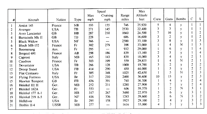
Figure 10.4(a) World War II aircraft
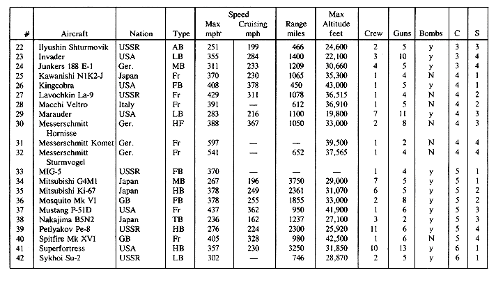
Figure 10.4(a). World War II aircraft

Aus. Australia HF heavy fighter
AB attack bomber LB light bomber
Br bomber MB medium bomber
C cylinder NB night bomber
FB fighter bomber NF night fighter
Fr fighter N no
GB Great Britain S surface
Ger. Germany y yes
HB heavy bomber
Figure 10.4(a) File of some World War II aircraft.
cylinder highest key value
----------------------------------
1 Bregeut 691
2 Heinkel III H
3 Junkers 188 E-l
4 Messerschmitt Sturmvogel
5 Spitfire Mk XVI
6 Vengeance
Figure 10.4(b) Cylinder index for file of figure 10.4(a)
surface highest key value
--------------------------
1 Mitsubishi G 4M1
2 Mosquito MkV1
3 Nakajima B5N2
4 Spitfire MkXVI
Figure 10.4(c) Surface index for cylinder 5.

Figure 10.5 Using an Array of Pointers to Permit Binary Search with Variable Length Key Values
10.2.2 Hashed Indexes
 and n be as defined in section 9.3. For a given
  and n we have
  = n/(bs), and so the product bs is determined. In the case of a hash table maintained in internal memory we chose the number of slots per bucket, s, to be 1. With this choice of s, the expected number of buckets accessed when open linear addressing is used is (2 -
  )/(2 - 2
 ), and 1 +
  /2 when chaining is used to resolve overflows. Since individual bucket accesses from a disk are expensive, we wish to explore the possibility of reducing the number of buckets accessed by increasing s. This would of necessity decrease b, the number of buckets, as bs is fixed. We shall assume that when chaining is used, the home bucket can be retrieved with one access. The hash table for chaining is similar to that for linear open addressing. Each bucket in the hash table, i.e. each home bucket, has s slots. Each such bucket also has a link field. This differs from the organization of section 9.3.2 where s = 0 for home buckets using chaining. Remaining buckets on individual chains have only one slot each and require additional accesses. Thus, if the key value X is in the i'th node on a chain (the home bucket being the 1st node in the chain), the number of accesses needed to retrieve X is i. In the case of linear open addressing if X is i buckets away from the home bucket, f(X), then the number of accesses to retrieve X is 1 + i.
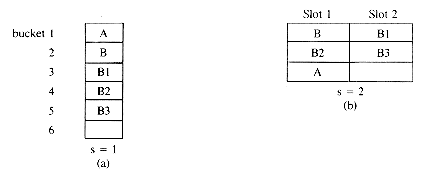
Figure 10.6 Hash Tables With s = 1 and 2.
 f (X)/2
 the assignment of key values to buckets is as in figure 10.6(b). The number of bucket retrievals needed now is 1 (for each of B and B1) + 2(for each of B2 and B3) + 3(for A) = 9. Thus the average number of buckets retrieved is reduced from 11/5 per search to 9/5 per search. The buckets of figure 10.6(b) are twice as big as those of figure 10.6(a). However, unless the bucket size becomes very large, the time to retrieve a bucket from disk will be dominated largely by the seek and latency time. Thus, the time to retrieve a bucket in each of the two cases discussed above would be approximately the same. Since the total average search time is made up of two components--first, the time, tr, to read in buckets from disk and second, the time, tp, to search each bucket in internal memory--we should choose b and s so as to minimize a (tr + tp) where a = average number of buckets retrieved. Using a sequential search within buckets, the time tp is proportional to s. Thus the average tp for figure 10.6(b) is one and a half times that for figure 10.6(a). When s is small and the hash table is on a disk, we have tr >> tp and it is sufficient to minimize a
  tr. Let us contrast this to the situation in section 9.3 where tr and tp are comparable. The table of figure 10.6(a) can be searched with an average of 11/5 key comparisons and accesses. The table of figure 10.6(b) requires 1 comparison to find B, 2 for B1, 3 for B2, 4 for B3 and 5 for A for a total of 15 comparisons. This implies an average of 3 comparisons per search. In this case the search time has actually increased with the increase in s. But, when the table is on disk, the average times are roughly 11tr/5 and 9tr/5, and the table with s = 2 gives better performance. In general, we can conclude that increasing s while maintaining b
  s fixed reduces a (see figure 10.7).
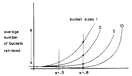
Figure 10.7
 =.5
=.5 , the average number of bucket accesses decreases with increasing s. Moreover, for s
  10, the average number of accesses for open linear addressing is roughly the same as for chaining. This together with our earlier observation that unless care is taken while using chaining, successive accesses will access random parts of the disk, while in the case of open linear addressing consecutive disk segments would be accessed, leads us to the conclusion that with suitable
  and s linear addressing will outperform chaining (contrast this with the case of internal tables).
 tt where ts, tl and tt are the seek time, latency time and transmission time per slot respectively. When the seek time is very large relative to tt the optimal s would tend to be larger than when ts is very small compared to tt (as in the case of a drum). Another consideration is the size of the input buffer available. Since the bucket has to be read into some part of internal memory, we must set aside enough space to accomodate a bucket load of data.
 = loading factor = (number of entries)/(number of slots in hash table)
 C uses more space than L as overflows are handled in a separate area.
Figure 10.8 Observed average number of bucket accesses for different
 and s. (Condensed from Lum, Yuen and Dodd: Key to Address Transform techniques: A fundamental performance study on large existing formatted files. CACM, Vol. 14, No. 4, Apr, 1974.)
10.2.3 Tree Indexing--B-Trees
 m. If T is empty, (i.e., T = 0) then T is an m-way search tree. When T is not empty it has the following properties:
 i
i  n are pointers to the subtrees of T and the Ki, 1
  i
i  n are key values; and 1
  n < m.
 i < n
i < n i < n
i < n i
i  n are also m-way search trees.
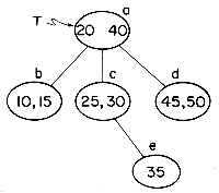
schematic
node format
------------------------
a 2,b,(20,c),(40,d)
b 2,0,(10,0),(15,0)
c 2,0,(25,0),(30,e)
d 2,0,(45,0),(50,0)
e 1,0,(35,0)
Figure 10.9 Example of a 3-way search tree.
 X < Ki+1 (for convenience we use K0 = [-
 ] and Kn+1 = [+
 ] where [-
 ] is smaller than all legal key values and [+
  ] is larger than all legal key values). In case X = Ki then the search is complete. If X
  Ki then by the definition of an m-way search tree X must be in subtree Ai if it is in the tree. When n (the number of keys in a node) is "large," the search for the appropriate value of i above may be carried out using binary search. For "small" n a sequential search is more appropriate. In the example if X = 35 then a search in the root node indicates that the appropriate subtree to be searched is the one with root A1 = c. A search of this root node indicates that the next node to search is e. The key value 35 is found in this node and the search terminates. If this search tree resides on a disk then the search for X = 35 would require accessing the nodes a, c and e for a total of 3 disk accesses. This is the maximum number of accesses needed for a search in the tree of figure 10.9. The best binary search tree for this set of key values requires 4 disk accesses in the worst case. One such binary tree is shown in figure 10.10.
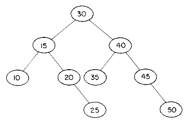
Figure 10.10 Best AVL-tree for data of figure 10.9
 i
i  n are the addresses of root nodes of subtrees. Since these nodes are also on a disk, the Ai are cylinder and surface numbers.
procedure MSEARCH(T,X)
//Search the m-way search tree T residing on disk for the key
value X. Individual node format is n,A0, (K1,A1), ...,(Kn,An),
n < m. A triple (P,i,j) is returned. j = 1 implies X is found
at node P, key Ki. Else j = 0 and P is the node into which
X can be inserted//
1 P
 T; K0
T; K0  [-
[- ]; Q
]; Q  0 //Q is the parent of P//
2 while P
 0 do
0 do3 input node P from disk
4 Let P define n, A0,(K1,A1), ..., (Kn,An)
5 Kn+1
 [+
[+ ]
]6 Let i be such that Ki
 X < Ki+1
7 if X = Ki then [//X has been found// return (P,i,1)]
8 Q
 P; P
P; P  Ai
Ai9 end
//X not in T; return node into which insertion can take place//
10 return (Q,i,0)
11 end MSEARCH
 1 the maximum number of nodes is
  0
0 i
i h-1 mi = (mh - 1)/(m - 1). Since each node has at most m - 1 keys, the maximum number of entries in an m-way tree index of height h would be mh - 1. For a binary tree with h = 3 this figure is 7. For a 200-way tree with h = 3 we have mh - 1 = 8 X 10⁶ - 1
 1 and satisfies the following properties:
 m/2
m/2 children
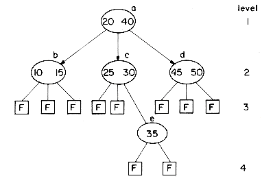
Figure 10.11 Search tree of figure 10.9 with failure nodes shown.
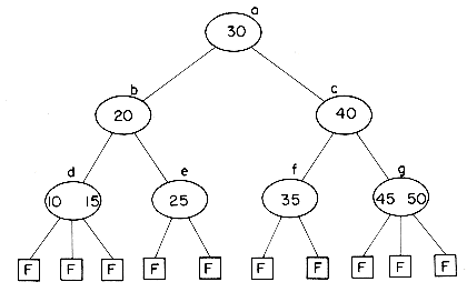
Figure 10.12 B-tree of order 3 for data of figure 10.9.
 m/2
m/2 children. Thus there are at least 2
  m/2
m/2 nodes at level 3. At level 4 there must be at least 2
 m/2
m/2 2 nodes, and continuing this argument, we see that there are at least 2
 m/2
m/2 l-2 nodes at level l when l > 1. All of these nodes are nonfailure nodes. If the key values in the tree are K1,K2, ...,KN and Ki < Ki+1, 1
 i<N then the number of failure nodes is N + 1. This is so because failures occur for Ki < X < Ki+1, 0
  i
i  N and K0 = [-
 ], KN+1 = [+
 ]. This results in N + 1 different nodes that one could reach while searching for a key value X not in T. Therefore, we have,
N + 1 = number of failure nodes in T
= number of nodes at level l + 1
 2
2 m/2
m/2 l - 1
l - 1and so, N
 2
2 m/2
m/2 l - 1 - 1, l
  1
1 log[m/2] {(N + 1)/2} + 1. The maximum number of accesses that have to be made for a search is l. Using a B-tree of order m = 200, an index with N
  2 X 10⁶ - 2 will have l
  log100 {(N+ 1)/2} + l. Since l is integer, we obtain l
  3. For n
  2 X 10⁸ - 2 we get l
  4. Thus, the use of a high order B-tree results in a tree index that can be searched making a very small number of disk accesses even when the number of entries is very large.
 i < m. If the Ki are at most
  characters long and the Ai and Bi each
  characters long, then the size of a node is approximately m(
 + 2
+ 2 ) characters. The time, ti, required to read in a node is therefore:
ti = ts + tl+ m(
 + 2
+ 2 ) tc
) tc= a + bm
where a = ts + tl = seek time + latency time
b = (
 + 2
+ 2 )tc and tc = transmission time per character
 = a + bm + c log2 m + d
(10.1)


(10.2)
 a = 0.035 sec. Assuming each key value is at most 6 characters long and that each Ai and Bi is 3 characters long,
  = 6 and
  = 3. If the transmission rate tc = 5 x 10⁻⁶ sec/character (corresponding to a track capacity of 5000 characters), b = (
 + 2
+ 2 )tc = 6 X 10⁻⁵ sec. The right hand side of equation (10.2) evaluates to
(10.3)
 [50,400]. In case the lowest value of m in this region results in a node size greater than the allowable capacity of an input buffer, the value of m will be determined by the buffer size.
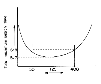
Figure 10.13 Plot of (35 + .06m)/log2 m
m,A0,(K1,A1) ...,(Km,Am)
and Ki < Ki+1, 1
 i < m.
node P:
 m/2
m/2 - 1, A0,(K1,A1), ...,(K
 m/2
m/2 -1, A
-1, A m/2
m/2 -1)
-1)(10.4)
node P': m -
 m/2
m/2 ,A
,A m/2
m/2 , (K
, (K m/2
m/2 +1,A
+1,A m/2
m/2 +1), ...,(Km,Am)
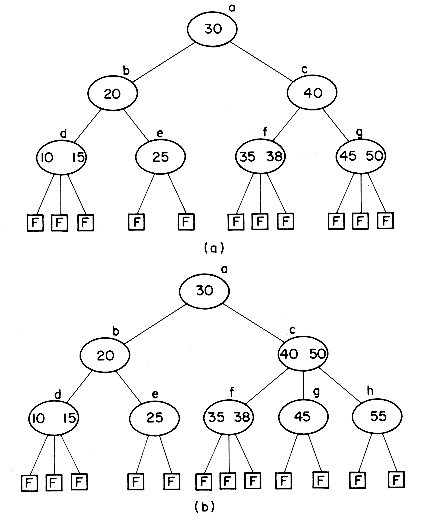
Figure 10.14 Insertion into a B-tree of order 3
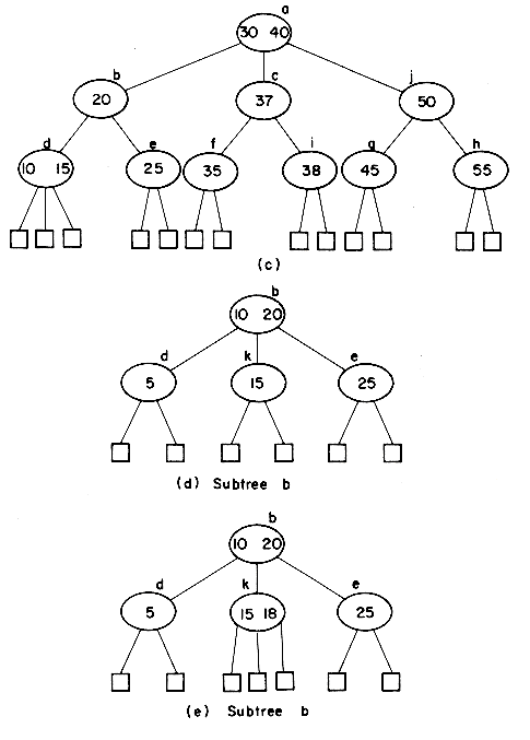
Figure 10.14 continued
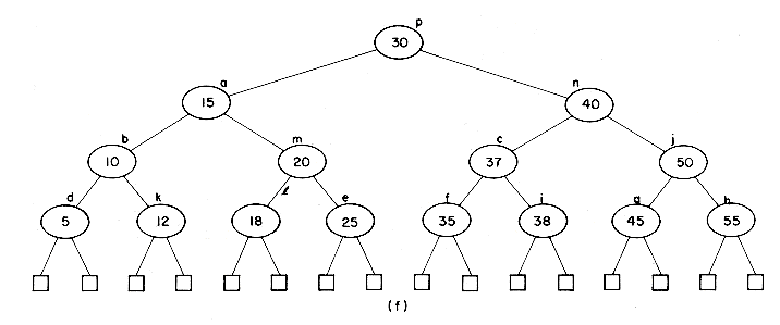
Figure 10.14 Insertion into a B-tree of Order 3 (continued)
procedure INSERTB(T,X)
//Key value X is inserted into the B-tree, T, of order m. T
resides on a disk.//
1 A
 0; K
0; K  X //(K,A) is tuple to be inserted//
2 (P,i,j,)
 MSEARCH(T,X) //P is node for insertion//
3 if j
 0 then return //X already in T//
4 while P
 0 do
0 do5 insert (K,A) into appropriate position in P. Let the resulting
node have the form: n,A0, (K1,A1), ..., (Kn,An).
6 if n
 m - 1 then [//resulting node is not too big//
output P onto disk; return]
//P has to be split//
7 Let P and P' be defined as in equation 10.4
8 output P and P' onto the disk
9 K
 K
K m/2
m/2 ; A
; A  P'; P
P'; P  PARENT(P)
10 end
//new root is to be created//
11 create a new node R with format 1,T,(K,A)
12 T
 R; output T onto disk
13 end INSERTB
 l. The maximum number of accesses needed is therefore 3l + 1. Since in most practical situations l will be at most 4, this means about thirteen accesses are needed to make an insertion in the worst case.
 m/2
m/2 - 1)(p - 1)
 m/2
m/2 - 1 key values. The average number of splittings, s, may now be determined
s = (total number of splittings)/N
 (p - 2)/ {1 + (
 m/2
m/2 - 1)(p - 1)}
< 1/(
 m/2
m/2 - 1).
- 1). l + 1.
Figure 10.15 B-trees of order 3
 m/2
m/2 - 1. An examination of g's
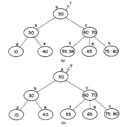
Figure 10.16 Deletion from a B-tree of order 3 (Failure nodes have been dispensed with)
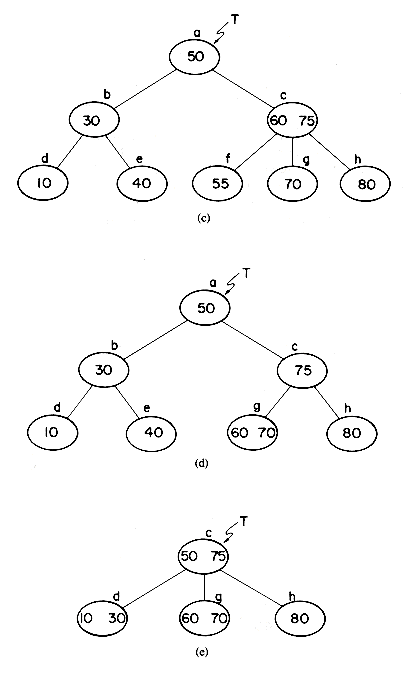
Figure 10.16 Deletion from a B-tree of order 3 (continued)

 m/2
m/2 keys, and the smallest key value in h, i.e., 75 is moved up to the parent node c. The value 70 is moved down to the child node g. As a result of this transformation, the number of key values in g and h is
 m/2
m/2 - 1, the number in c is unchanged and the tree retains its B-tree properties. In the search for X = 65, the nodes a, c and g had to be accessed. If all three nodes are retained in memory then from c the address of h the nearest right sibling of g is readily determined. Node h is then accessed. Since three nodes are altered (g, c, and h), three more accesses are to be made to rewrite these nodes onto disk. Thus, in addition to the accesses made to search for X = 65, four more accesses need to be made to effect the deletion of X = 65. In case g did not have a nearest right sibling or if its nearest right sibling had only the minimum number of key values i.e.
  m/2
m/2 - 1 we could have done essentially the same thing on g's nearest left sibling. In deleting X = 55 from the tree of figure 10.16(c), we see that f's nearest right sibling, g, has only
  m/2
m/2 - 1 key values and that f does not have a nearest left sibling. Consequently, a different transformation is needed. If the parent node of f is of the form n,A0, (K1,A1), ... (Kn,An) and A1 = g then we can combine the remaining keys of f with the keys of g and the key Ki into one node, g. This node will have (
 m/2
m/2 - 2)+ (
 m/2
m/2 - 1) + 1 = 2
 m/2
m/2 - 2
- 2  m - 1 key values which will at most fill the node. Doing this with the nodes f, g and c results in the B-tree of figure 10.16(d). Three additional accesses are needed (one to determine that g was too small, one to rewrite each of g and c). Finally, let us delete X = 40 from node e of figure 10.16(d). Removal of this key value leaves e with
  m/2
m/2 - 2 key values. Its nearest left sibling d does not have any extra key values. The keys of d are combined with those remaining in e and the key value 30 from the parent node to obtain the full node d with values 10 and 30. This however leaves b with o
When the key value X being deleted is not in a leaf node, a simple transformation reduces this deletion to the case of deletion from a leaf node. Suppose that Ki = X in the node P and P is of the form n,A0, (K1,A1), ..., (Kn,An) with 1
  i
i  n. Since Pis not a leaf node, Ai
  0. We can determine Y, the smallest key value in the subtree Ai. This will be in a leaf node Q. Replace Ki in P by Y and write out thed new P. This leaves us with the problem of deleting Y from Q. Note that this retains the search properties of the tree. For example the deletion of X = 50 from the tree of figure 10.16(a) can be accomplished by replacing the 50 in node a by the 55 from node f and then proceeding to delete the 55 from node f (see figure 10.17).
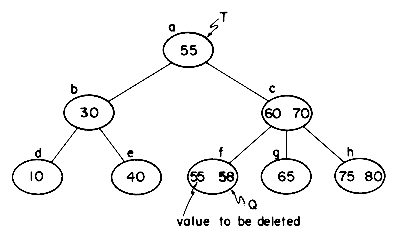
Figure 10.17 Deleting 50 from node a of figure 10.16(a)
procedure DELETEB(T,X)
//delete X from the B-tree, T, of order m. It is assumed that
T reside on a disk//
1 (P,i,j)
 MSEARCH (T,X)
2 if j
 1 then return //X not in T//
3 let P be of the form: n,Ao,(K1,A1), ..., (Kn,An) and Ki = X
4 if Ao
 0 then [//deletion from non leaf, find key to move up//
5 Q
 Ai //move to right subtree//
6 loop
7 let Q be of the form:
n',A'0, (K'1,A'1) ..., (K'n,A'n')
8 if A'0 = 0 then exit //Q is a leaf
node//
9 Q
 A'0
A'010 forever
11 replace Ki in node P by K'1 and write the
altered node P onto disk.
12 P
 Q, i
Q, i  1;
1;13 let n,A0,(K1,A1), ...,(Kn,An) be as
defined by the new P]
//delete Ki from node P, a leaf//
14 from P: n,A0, (K1,A1), ...,(Kn,An) delete (Ki,Ai) and replace n
by n - 1
15 while n <
 m/2
m/2 - 1 and P
  T do
T do16 if P has a nearest right sibling, Y, then
17 [let Y: n",A"0, (K"1,A"1), ...,(K"n",A"n") and
18 let Z: n',A'0, (K'1,A'1),...,(K'n',A'n') be the parent of P
and Y
19 let A'j = Y and A'j-1 = P
20 if n"

 m/2
m/2 then [//redistribute key values//
21 //update P// (Kn+1, An+1)
 (K'j, A"0);
n
 n + 1
n + 122 //update Z// K'j
 K"1
K"123 //update Y// (n",A"0,(K"1,A"1),...)

(n" - 1,A"1,(K"2,A"2)...)
24 output nodes P,Z and Y onto
disk
25 return]
//combine P, K'j and Y//
26 r
 2
2 m/2
m/2 - 2
- 227 output r,A0,(K1,A1) ... (Kn,An),(K'j,A"0),(K"1,A"1),
... (K"n",A"n") as new node P
28 //update// (n,A0, ...,)
 (n' - 1,A.'0,...,(K'j-1,A'j-1),
(K'j+1,A'j+1)...)
29 P
 Z]
Z]else
30 [//P must have a left sibling//
this is symmetric to lines 17-29
and is left as an exercise]
31 end
32 if n
 0 then [output P: (n,A0, ...,(Kn,An)]
33 else [T
 A0]
A0]34 end DELETEB
 1,
1, 2, ...,
 n, (K1,A1), ...,(K n,An) where
  i is the address of Ki in internal memory i.e. Ki = memory (
 i). In this case a binary search of the node can still be made. The use of variable size nodes is not recommended since this would require a more complex storage management system. More importantly, the use of variable size nodes would result in degraded performance during insertion. For example, insertion of X= 85 intothe 2-3 tree of figure 10.16(e) would require us to request a larger node, j, to accomodate the new value being added to the node h. As a result, node c would also be changed since it contains a pointer to h. This pointer must be changed to j. Consequently, nodes of a fixed size should be used. The size should be such as to allow for at least m - 1 key values of the largest size. During insertions, however, we can relax the requirement that each node have
  m - 1 key values. Instead a node will be allowed to hold as many values as can fit into it and will contain at least
  m/2
m/2 - 1 values. The resulting performance will be at least as good as that of a B-tree of order m. Another possibility is to use some kind of key sampling scheme to reduce the key value size so as not to exceed some predetermined size d. Some possibilities are prefix and suffix truncation, removing vowels, etc. Whatever the scheme used, some provision will have to be made for handling synonyms (i.e., distinct key values that have the same sampled value). Key sampling is discussed further in section 10.2.4.
10.2.4 Trie Indexing
 2 in which the branching at any level is determined not by the entire key value but by only a portion of it. As an example consider the trie of figure 10.18. The trie contains two types of nodes. The first type we shall call a branch node and the second an information node. In the trie of figure 10.18 each branch node contains 27 link fields. All characters in the key values are assumed to be one of the 26 letters of the alphabet. A blank is used to terminate a key value. At level 1 all key values are partitioned into 27 disjoint classes depending on their first character. Thus, LINK(T,i) points to a subtrie containing all key values beginning with the i-th letter (T is the root of the trie). On the j th level the branching is determined by the j th character. When a subtrie contains only one key value, it is replaced by a node of type information. This node contains the key value, together with other relevant information such as the address of the record with this key value, etc. In the figure, branch nodes are represented by rectangles while ovals are used for information nodes.
procedure TRIE (T,X)
//Search a trie T for key value X. It is asssumed that branching
on the i-th level is determinded by the i-th character of the key
value.//
K
 X
X 
 ' ' //concatenate a blank to the end of X//
i
 1; P
1; P  T
Twhile P is a branch node do
C
 i-th character of K
P
 LINK (P,C);
  i + 1
i + 1end
if P = 0 or KEY (P)
 X then return (0) //X not in trie//
return (P)
end TRIE

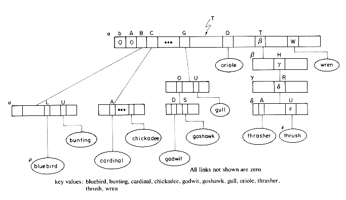
Figure 10.18 Trie created using characters of key value left to right, one at a time
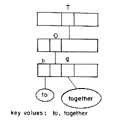
Figure 10.19 Trie showing need for a terminal character (in this case a blank).
 , where we discover that LINK(
 , 'O') = 0. Hence X is not in T and may be inserted here (see figure 10.23). Next, X = bluejay and a search of T leads us to the information node
  . A comparison indicates
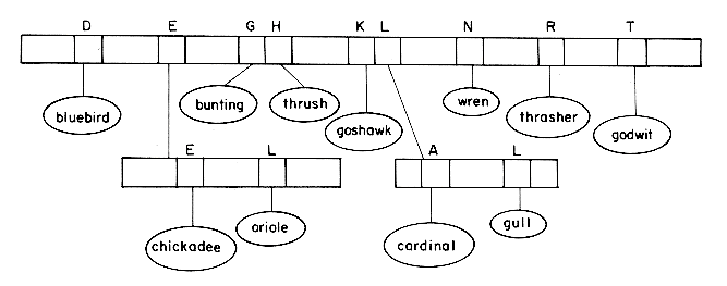
Figure 10.20 Trie constructed for data of figure 10.18 sampling one character at a time, right to left

Figure 10.21 An optimal trie for data of figure 10.18 sampling on first level done by using 4th character of key values.
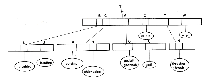
Figure 10.22 Trie obtained for data of figure 10.18 when number of levels is limited to 3. Key has been sampled left to right one character at a time.
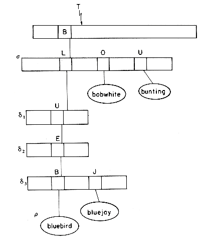
Figure 10.23 Section of trie of figure 10.18 showing changes resulting from inserting bobwhite and bluejay
 )
)  X. Both KEY(
 ) and X will form a subtrie of
  . The two values KEY(
 ) and X are sampled until the sampling results in two different values. The happens when the 5th letter of KEY(
 ) and X are compared. The resulting trie after insertion is in figure 10.23.
 ,'O') = 0. No other changes need be made. Next, let us delete 'bluejay.' This deletion leaves us with only one key value in the subtrie,
  3. This means that the node
  3 may be deleted and
  moved up one level. The same can be done for nodes
  1 and
1 and  2. Finally, the node
  is reached. The subtrie with root
  has more than one key value. Therefore
  cannot be moved up any more levels and we set LINK(
 ,'L') =
  . In order to facilitate deletions from tries, it is useful to add a COUNT field in each branch node. This count field will at all times give us the number of information nodes in the subtree for which it is the root. See exercise 26 for more on tries.
10.3 FILE ORGANIZATIONS
10.3.1 Sequential Organizations
10.3.2 Random Organization
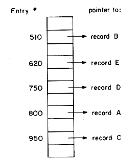
Figure 10.24 Direct Access Index for Data of Figure 10.1.
 employee number
  800. To do (i) we will need to know the maximum employee number in the file or else examine every node. If the maximum employee number is known then (i) becomes similar to (ii), so lets look at (ii). With direct addressing and hashing, we would have to search for records with employee number = 301, 302, ... 800, a total of 500 independent searches. The number of records satisfying the query may be much smaller (even 0). In the case of ISAM we could in three accesses locate the record (if one exists) having the smallest employee number satisfying the query and retrieve the remaining records one at a time. The same is possible when a search tree type directory (index) is maintained.
10.3.3 Linked Organization
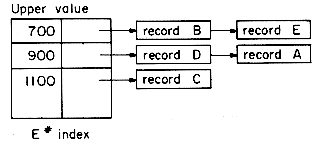
Figure 10.25
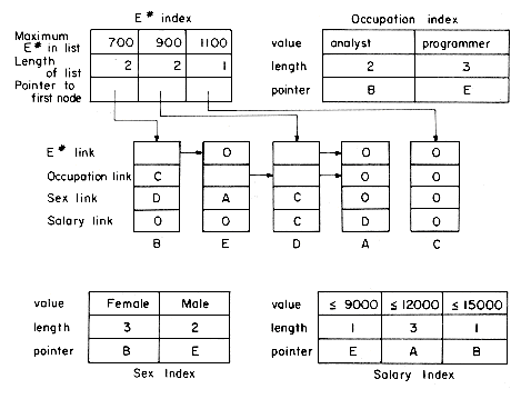
Figure 10.26 Multilist representation for figure 10.1
 10i=1 ni entries while the original indexes had a total of
  10i=1 ni entries. Also, handling simple queries becomes more complex if the individual key indexes are no longer retained (see the exercies).
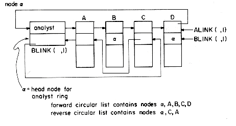
Figure 10.27 Coral ring for analysts in a hypothetical file.
10.3.4 Inverted Files

Figure 10.28 Indexes for fully inverted file
10.3.5 Cellular Partitions
10.4 STORAGE MANAGEMENT
Fixed Size Nodes
procedure GETNODE(I)
if AV = 0 then [print "no more nodes;" stop]
I
 AV; X
AV; X  GET(AV); AV
  LINK(X)
end GETNODE
procedure RET(I)
LINK(I)
 AV; WRITE(I); AV
  I
Iend RET
Variable Size Nodes
Garbage Collection and Compaction
REFERENCES
EXERCISES
E# NAME Occupation Location
A 10 JAMES PROG MPLS
B 27 SHERRY ANAL NY
C 39 JEAN PROG NY
D 50 RODNEY KEYP MPLS
E 75 SUSAN ANAL MPLS
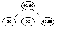
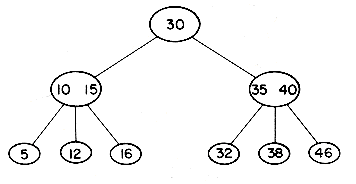
 (number of key values in the subtree Aj + 1).) What is the worst case computing times of your algorithms?
 (2m - 2)/3
 ,
,  (2m - 1)/3
 and
and  2m/3
2m/3 key values. Figure 10.29 below describes this splitting procedure when P' is P's nearest right sibling.
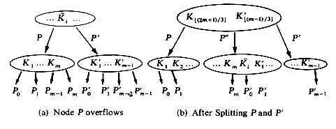
Figure 10.29 Splitting P and nearest right sibling P'
 1. When T is not empty then the extended tree T (i.e., T with failure nodes added) satisfies the following conditions:
 (2m - 2)/3
 + 1 children.
 (2m - 1)/3
 children each.
 (2m - 1)/3
 then
then 1 + logx{(N+1)/2}
 1 + (N - 1)/(x-1)
 i < j is the value of the largest key in the i'th subtree of P. Figure 10.30 shows two B'-trees of order 3. Notice that in a B'-tree the key values in the leaf nodes will be increasing left to right. Only the leaf nodes contain such information as the address of records having that key value. If there are n key values in the tree then there are n leaf nodes. Write an algorithm to search for X in a B'-tree T of order 3. Show that the time for this is O(log n).
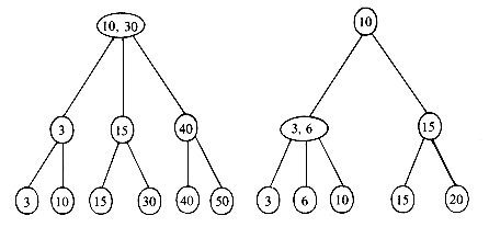
Figure 10.30 Two B'-trees of order 3
 1 and
1 and  2 each have only one child. Branch nodes with only one child may be eliminated from tries by maintaining a SKIP field with each node. The value of this field equals the number of characters to be skipped before obtaining the next character to be sampled. Thus, we can have SKIP (
 3) = 2 and delete the nodes
  1 and
1 and  2. Write algorithms to search, insert and delete from tries in which each branch node has a skip field.
 NY
NY


