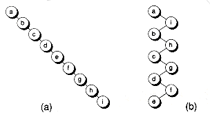
Figure 11.1 Degenerate trees.
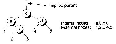
In this chapter, we'll draw internal nodes using circles, with letters as labels. External nodes are denoted by drawing links leading nowhere, and perhaps labelled using numbers, or they may not be drawn at all. Figure 11.3 shows a sample tree illustrating both internal and external nodes.
Sometimes we'll draw only a portion of a tree, with the top node of this portion having an implied parent (or no parent at all if it's the root). Subtrees are indicated using the same notation as external nodes, by drawing links leading nowhere and having numbers for labels. In fact, you can consider an external node to be an empty subtree.
There is a reason for treating external nodes and subtrees the same. In the tree transformations to come, we'll strive to maintain certain properties of the trees. In the drawings we'll show, those properties will be maintained regardless of whether labelled links are external nodes or subtrees, assuming the properties held before the transformations, of course.
There are two basic ways used to keep trees balanced:
1. Use tree rotations.
2. Allow nodes to have more than two children.
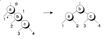
Certain types of tree-restructurings, known as rotations, can aid in balancing trees. Figure 11.4 illustrates the two types of single rotations.
The following sample code for single rotations uses generic Bnodeb pointers (as defined in Chapter 10), and assumes that all relevant pointers aren't null:
Another type of rotation is known as a double rotation. Figure 11.5 shows the two symmetrical cases. Here's the sample code:
Both single and double rotations have one important feature: inorder traversals of the trees before and after the rotations are preserved. Thus, rotations help balance trees, but still maintain the binary search tree property.
Rotations don't guarantee a balanced tree, however. For example, Figure 11.6 shows a right rotation that makes a tree more unbalanced. The trick lies in determining when to do rotations and what kind of rotations to do. The red-black trees discussed later have certain rules used to determine when and how to rotate.
We can also help keep trees balanced by allowing nodes to have more than two children. Instead of using binary trees, we can have multi-way trees. A multiway tree node with n children is known as an n-node. An n-node has n-1 keys that are used for comparisons. For example, Figure 11.7 shows a 4-node with three keys. Nodes with keys less than a are inserted down subtree 1. Nodes greater than a but less than b are inserted down subtree 2. Nodes greater than b but less than c are inserted down subtree 3. And finally, nodes with keys greater than c are inserted down subtree 4.
For a given set of keys, a balanced multi-way tree will have a smaller height than a balanced binary tree, because more keys can be stored per node. In our 4-node example, we can collapse what would be two or three levels of a binary tree into one level. This ability to collapse levels makes multi-way trees easier to balance than binary trees.
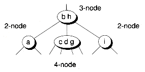
One special type of multi-way tree is known as a B-tree, which we'll study in depth in Chapter 14. A B-tree of order m has nodes that can have up to m children. In this chapter, we'll look at B-trees of order four. Such trees are often called 2-3-4 trees. A 2-3-4 tree has three types of nodes: 2-nodes (that is, binary nodes), 3-nodes, and 4-nodes. Figure 11.8 shows a sample 2-3-4 tree.
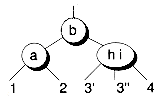
Insertion into a 2-3-4 tree works as follows: First, search the tree looking for the node to insert the new key into. If the candidate is a 2-node, then insert the key, making the node a 3-node. If the candidate is a 3-node, then insert the key, making the node a 4-node. If the candidate is a 4-node, it is full and must be split. The node is split into two 2-nodes, with the left key going to the left 2-node, the middle key moving up to the parent node, and the right key going to the right 2-node. The key to be inserted is then added to the appropriate 2-node.
Figure 11.9 shows how to split a 4-node, where there is no parent. The middle key is pushed up to a new root. If there is a parent, the parent itself may have to be split. The splitting process then propagates up the tree. Thus, insertion consists of a top-down searching pass, followed by a bottom-up splitting pass. Figure 11.10 shows an example of building a 2-3-4 tree using the same pathological sequence a-i-b-h-c-g-d-f-e that we've used before.
One consequence of 4-node splitting is that the tree grows upward, rather than downward as in a binary tree. As a result, the external nodes of a 2-3-4 tree are always on the same level, and the tree is quite balanced. (These same properties hold in general for all B-trees.)
We won't actually implement 2-3-4 trees using the three different types of nodes. You can actually represent 2-3-4 trees using binary nodes, as we'll discuss next.
A red-black tree is a binary representation of a 2-3-4 tree. (Red-black trees can be used to represent a wide variety of trees. See [GuibSedg 78].) In a red-black tree, the links are given the colors red and black. These colors are used in mapping the 2-node, 3-node, and 4-nodes of a 2-3-4 tree into binary nodes. Figure 11.11 shows the mappings. In this figure and others to follow, red links are shown with thick lines, whereas black links are shown with lines of normal thickness. A node having a black parent link is referred to as a black node. A node with a red parent link is a red node. In the diagrams, we chose to color the links using thin/thick lines (rather than actually coloring the nodes).
The red-black mappings work as follows: a 2-node is represented using a single binary node with two black children. A 3-node is represented as a pair of binary nodes--one red, one black. Hence there is a red link between the nodes. Note that 3-nodes can be represented with two different orientations. The orientation used depends on the balancing required, as you'll see later. A 4-node is represented as a set of three binary nodes, with the parent node black and the child nodes red. Hence, two red links are used.
Three basic properties emerge from the way the red-black mappings are defined:
1. There's no way to have two red links in a row on any path in the tree. That's because there's no way to map this arrangement back to a 2-3-4 tree. (What kind of node would have both a red parent and a red child?)
2. The external nodes of a red-black tree have the same black-depth. The black-depth of a node is the number of black nodes found on the path from the root to that node. Remember that red links correspond to 3-nodes and 4-nodes, and thus don't contribute to the height of the equivalent 2-3-4 tree. This fact, coupled with the fact that external nodes of the 2-3-4 tree are at the same height, means that external nodes of a red-black tree have the same black-depth.
3. The root node is always black. Since the root doesn't have a parent, there's no way for it to have a red parent link.
Figure 11.12 shows the red-black tree equivalent of the tree given in Figure 11.10. Note that the red-black tree is structurally the same as the binary tree given earlier in Figure 11.2. The only difference is the coloring of the links. The link colors serve as guideposts in determining what kind of rotations to do when balancing the tree. Note that the external nodes all have a black-depth of 2. This corresponds to the height of the equivalent 2-3-4 tree.
The tree shown in Figure 11.12 is fairly balanced, but isn't as balanced as its 2-3-4 tree counterpart, and is twice as high. Why the difference? The 3-nodes and 4-nodes of the 2-3-4 tree must be simulated using multiple binary nodes, each set consuming two levels of the tree. However, it can be shown that no path in a red-black tree is longer than twice as long as the shortest path in the tree. Thus, although the red-black trees aren't perfectly balanced, their worst case isn't all that bad.
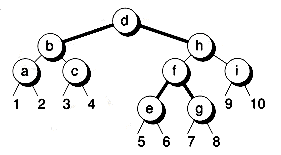
Figure 11.13 illustrates an illegal red-black tree, with two consecutive red links in a row (d-h and h-i). Also, the external nodes have different black-depths as indicated in the figure. The resulting tree is still a valid binary search tree, but because it doesn't have the strict red-black tree properties, updates to the tree (assuming they could even be done) would tend to produce an unbalanced tree.
We'll represent red-black tree nodes with the following RBnodeb and RBnode classes:
As with all designs, it's worthwhile to strive for data independence whenever possible. That's the purpose of the RBnodeb class. This class is derived from the Bnodeb class of Chapter 10, and adds a color field, but no other data. The color field represents the color of the link coming into the node--0 for red, 1 for black. We've represented color as a character, which represents additional overhead in every red-black node. Actually, only one bit is required. In your own classes, you may be able to arrange this bit to be stored in some unused location in the node's data field. An alternative representation would have colors associated with the child links, rather than the nodes themselves. However, this requires two bits per node, rather than one.
Since RBnodeb is derived from Bnodeb, it can be used in many generic binary tree functions--such as the tree-traversal functions or the tree-walking iterators. The RBnode class is a template derived from RBnodeb that adds data to the node. Unfortunately, an RBnode object cannot be substituted for a Bnode object (a binary node with data), since the info field of these two types of nodes is at a different offset in the node structure. As usual, convenience functions Left( ) and Right( ) are supplied to help alleviate type casting problems. The details are given on disk.
The RBtree class implements red-black trees as concrete data types, with the appropriate constructors, destructors, assignment functions, and other supporting functions. This class is very similar in design to the Bstree class developed in Chapter 10. We'll look only at the main operations of searching, inserting, and deleting. The remaining details are given on disk.
Complete code for red-black trees is given on disk in the files RBnode.h, RBtree.h, RBtreeb.cpp, and RBtree.mth. A test program is given in the files tstrb.cpp and tsttree.cpp. Many of the files from Chapter 10 are used as support files.
A red-black tree can be searched in the same way as an ordinary binary search tree, as the following Member( ) function shows. Note that the colors of the nodes are not used in the search. The fact that the tree is balanced in no way impinges on the searching code (other than to make the searches faster due to shorter trees, of course).
We described an insertion process earlier for 2-3-4 trees that involved two passes: a top-down pass to determine where the new key should go, and a bottom-up pass to handle any full 4-nodes that need to be split. It's possible to do the insertion in a single top-down pass, and that's the method we'll use for red-black trees.
Single-pass top-down insertions can be done by ensuring that the new key won't be added to a full leaf node. We can do this by splitting any 4-node we see on the path to the leaf into two 2-nodes. Splitting a 4-node, as represented with red-black nodes, is particularly easy. As Figure 11.14 illustrates, the process involves three color flips, and that's all. Note how the two child links are turned to black, but the parent link is turned to red. This is done to preserve the black-depths of the external nodes 1, 2, 3, and 4 (which may be subtrees). In all the red-black tree transformations to follow, we always ensure that the relative black-depths of the external nodes or subtrees are preserved. That way, we can guarantee that the new tree will still be a valid red-black tree. A side effect is that the tree will be kept as balanced as possible.
Since the top node of the split 4-node becomes red during a split, a problem occurs if its parent is also red, because we then end up with two reds in a row. This must be fixed by using appropriate rotations. We'll look at all the possible cases now.
Figure 11.15 shows the two orientations of a 4-node connected to a 2-node. In both orientations, we end up with a 3-node having two 2-nodes as children when the 4-node is split. The results are still legal red-black trees, so nothing else has to be done.
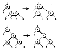
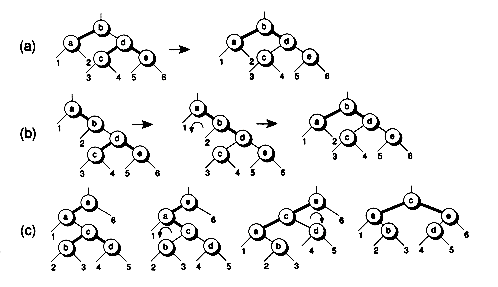
Figure 11.16 illustrates the three cases that occur when a 4-node is connected to a 3-node. Here, the 4-node can be the left child, middle child, or right child of the 3-node. Recall that, in a red-black representation, a 3-node has two orientations. Thus, there are six cases to consider in the red-black tree representations. In Figure 11.17, we show three of these cases. Figures 11.17(a) and 11.17(b) show the two cases that arise when the 4-node is the right child of the 3-node, with the two possible 3-node orientations. Not shown are the two symmetrical cases that occur when the 4-node is the left child. Figure 11.17(c) shows one of the cases that occurs when the 4-node is the middle child. Again, there is a symmetrical case not shown.
In Figure 11.17(a), splitting the 4-node leads to a valid red-black tree, so nothing more needs to be done other than the color flips. However, in Figures 11.17(b) and 11.17(c), splitting the 4-node leads to trees having two reds in a row. Thus, after the color flips, rotations must be performed to restore the redblack property. For the case in Figure 11.17(b), a single rotation is needed. For the case in Figure 11.17(c), a double rotation is required. Note that the colors "follow" the rotations. In all three figures, you should verify for yourself that the black-depths of the external nodes are preserved.
We don't need to be concerned about any 4-node to 4-node cases. That's because the parent 4-node will be split before we get to the child 4-node.
The insertion code is given in the routines Add( ) and InsBalance( ). The Add( ) function walks down the tree looking for a place to insert the new key, splitting any 4-nodes along the way. After a split, there may be two red nodes in a row. If so, a call is made to InsBalance( ), which performs the proper rotations. Add( ) keeps track of the current node t, its parent p, grandparent g, and great-grandparent gg, all of which are needed to do the rotations. To make the call to InsBalance( ) efficient, the pointers are packaged up into the structure PtrPak, and a single parameter is then passed for these pointers. A pointer to the root node is also passed, since the root may change due to a rotation.
When the bottom of the tree is reached and the key to be inserted isn't found, a new node is added, colored red, and if needed, an adjusting balance is performed. (It's useful to pretend the new node is a black 4-node that is split, with its colors adjusted like any split 4-node.) If the key already exists, a flag is set to indicate that. It's important to realize that Add( ) may cause the tree to be restructured even if the key already exists.
If the root is a 4-node before the insertion, it will be "split" and the root becomes red. The Add( ) function corrects this situation by always setting the root black. During this color change, the black-depths of the external nodes increase by one, but the tree remains valid, since the black-depths are still all identical.
Figure 11.18 shows an example of building a red-black tree using the pathological insertion sequence a-i-b-h-c-g-d-f-e. The resulting tree is equivalent to the 2-3-4 tree in Figure 11.10, except that the 4-node root has been split into two 2-nodes. Note that the tree is quite balanced.
Recall from Chapter 10 how deletions work in a regular binary search tree: The basic idea is to swap the key of the node to be deleted with the key of the node's successor. (We used pointer surgery rather than actually swapping keys. Also, the predecessor could be used instead of the successor.) Then, the successor is deleted, which reduces to the case of removing a node with at least one null child. As we showed in Chapter 10, this case is easy to handle.
Deleting from a red-black tree works very much the same way. There's a catch, though: If the successor is black, and we remove it from the tree, then all the nodes under the successor (including any external nodes) will have their black-depths reduced by one, resulting in an illegal red-black tree. When the successor is red, this problem doesn't occur.
Thus, we must somehow handle the case where the successor is black. One approach is to ensure that the successor is always red. This can be done by a single top-down pass, in the following way: an "extra" red can be pushed down the tree as we work our way towards the successor. (We must also keep track of the node to be deleted when it is encountered.) Thus, when the successor is reached, it's guaranteed to be red. The trick is to keep the tree a valid red-black tree. We accomplish this by doing appropriate rotations and color flips, keeping the black-depths of all external nodes identical. Recall that this approach keeps the leaves of the equivalent 2-3-4 tree at the same level, and thus the tree remains fairly balanced.
From the viewpoint of the equivalent 2-3-4 tree, pushing an extra red down the tree involves three types of operations:
1. Merging two 2-nodes into a single 4-node.
2. Flipping the red-black orientations of 3-nodes.
3. Rotating 3-nodes and 4-nodes from one side of the tree to the other. The rotations always take place toward the side containing the current node being traversed.
Figure 11.19 shows examples of the first and third cases. The second case is not shown since it doesn't structurally change the equivalent 2-3-4 tree; it just changes the orientation of the red-black interpretation. Please note that these cases have other orientations not shown in the figure. It's interesting that the act of merging 2-nodes into 4-nodes is exactly the opposite of what we do during insertions, where 4-nodes are split in two. Thus, deletions are the opposite of insertions, with the added step of pushing an extra red down the tree.
Figures 11.20, 11.21, and 11.22 show the orientations and transformations for the three balancing operations, in terms of red-black trees. In all three figures, the node labelled t is the current node being traversed, p is its parent, g is its grandparent, s is its sibling, and ls and rs are the left and right children of s. Vertical lines shown for grandparents mean that the parent node can either be on the left or right. Dashed lines indicate links that can be either red or black. You should verify for yourself that the transformations shown preserve the relative black-depths of all external nodes.
The algorithm for deleting a node from a red-black tree is split into four procedures: Delete( ), Detach( ), DelBalance( ), and DoReplacement( ). The Delete( ) function (not given) calls Detach( ) to detach the node from the tree, and then frees the node. Detach( ) works by walking the tree from the top down, searching for the node to delete, recording its location, and then continuing to walk the tree pretending that the node wasn't found. By doing this, when a null node is reached, the current parent will be the successor node. All the while, rotations and color flips are done by calling DelBalance( ). At the end, the DoReplacement( ) function is called to "swap" the key of the node to delete with the key of the successor. (Actually, the replacement is done by pointer surgery, rather than actually swapping the keys.)
To save function-calling overhead, the necessary pointers are packaged into a PtrPak structure (defined earlier), which is then passed via another pointer. The root is also passed in case it needs to be updated.
Here are the Detach( ), DelBalance( ), and DoReplacement( ) functions. Note that DelBalance( ) and DoReplacement( ) are written using generic RBnodeb pointers and are thus shared by all red-black trees, regardless of the type of data they hold.
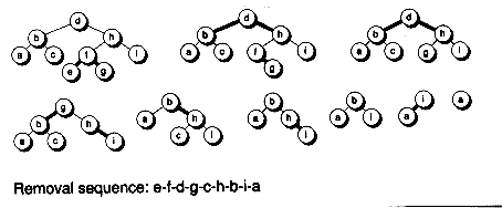
Figure 11.23 shows the tree given in Figure 11.18 as it is destroyed by removing nodes in the sequence e-f-d-g-c-h-b-i-a.
There's one curious fact about the deletion algorithm. Even if the node to be deleted from the tree isn't found, the tree structure may still be modified, as node merging and tree rotations are performed in anticipation of a node deletion. If the Detach( ) routine is called repeatedly this way, the tree structuring will eventually converge onto a "stable" configuration.
The insertion and deletion routines given in this chapter are complicated by the need to test for boundary conditions, such as non-existent parents, grandparents, children, or siblings. You'll notice explicit tests for null pointers in the code to handle these conditions. The routines can be simplified somewhat by creating a special sentinel node to be used for all otherwise non-existent nodes. This node can be colored black, and all null child links can be modified to point to this sentinel. For more details on using artificial nodes like this, see [GuibSedg 78].
If you need to ensure that a binary search tree never degenerates to worst-case scenarios, then a 2-3-4 tree, as implemented using a binary red-black tree, is the data structure of choice. Recall that 2-3-4 trees are B-trees of order 4. It's possible to generalize the technique behind red-black trees to work for B-trees of any order, by having links with more than two color choices. However, it's not really beneficial to do this; it's better instead to implement B-trees directly with multi-way nodes. This is due to the I/O paging characteristics of most disk devices. For example, there will be some page size that corresponds to a B-tree node of a certain order that will be optimal for any given disk. We'll explore B- trees on disk in Chapter 14. Just remember that red-black trees are efficient implementations of B-trees of order 4 that happen to perform well in memory.
Figure 11.2 A balanced tree.
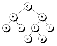
Figure 11.3 Internal and external nodes.
BALANCING ACTS
Tree Rotations
Bnodeb *RotateRight(Bnodeb *p, Bnodeb *t)
// Rotate right around p, assuming t is p's left child
// Returns t, which will be the new child of p's parent
{p->left = t->right;
t->right = p;
return t;
}
Bnodeb *RotateLeft(Bnodeb *p, Bnodeb *t)
// Symmetrical case
{p->right = t->left;
t->left = p;
return t;
}
Figure 11.4 Single rotations.
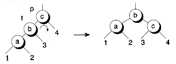
(a) Right rotation
(b) Left rotation
Bnodeb *RotateLeftRight(Bnodeb *g, Bnodeb *p, Bnodeb *t)
// Rotate first around p, then around g. Assumes p is left
// child of g, and t is the right child of p. Returns new
// child of g's parent.
{p->right = t->left;
t->left = p;
g->left = t->right;
t->right = g;
return t;
}
Bnodeb *RotateRightLeft(Bnodeb *g, Bnodeb *p, Bnodeb *t)
// Symmetrical case
{p->left = t->right;
t->right = p;
g->right = t->left;
t->left = g;
return t;
}
Figure 11.5 Double rotations.

(a) Left-right rotation

(b) Right-left rotation
Multi-Way Trees
Figure 11.6 An unbalancing rotation.

Figure 11.7 A 4-node.

Figure 11.8 A 2-3-4 tree.
RED-BLACK TREES
Figure 11.9 Splitting a 4-node.

(a) Original

(b) Split in two
(c) 'h' added
Figure 11.10 Building a 2-3-4 tree.

Figure 11.11 Red-black mappings for 2-3-4 nodes.
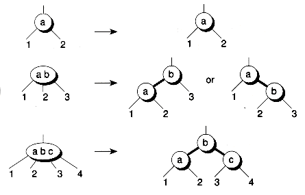
Figure 11.12 A red-black tree.
Red-Black Tree Classes
#define RED 0
#define BLACK 1
struct RBnodeb : Bnodeb {char color;
RBnodeb *&Left( );
RBnodeb *&Right( );
};
template<class TYPE>
struct RBnode : Rbnodeb {TYPE info;
RBnode( );
RBnode(const TYPE &x, char c, RBnode<TYPE> *1=0, RBnode<TYPE> *r=0);
RBnode<TYPE> *&Left( );
RBnode<TYPE> *&Right( );
};
Figure 11.13 An illegal red-black tree.

template<class TYPE>
class RBtree {protected:
RBnode<TYPE> *root;
// Other protected functions--such as AllocNode( ), DupTree( ),
// FreeNode( ), and DelTree( )...
public:
RBnode<TYPE> *Member(const TYPE &x);
RBnode<TYPE> *Add(const TYPE &x, int &existed);
RBnode<TYPE> *Detach(const TYPE &x);
int Delete(const TYPE &x);
// Constructor functions, plus other functions for copying,
// clearing, and deleting trees, and functions for handling
// min/max elements, and so forth...
};

Searching a Red-Black Tree
template<class TYPE>
RBnode<TYPE> *RBtree<TYPE>::Member(const TYPE &x)
// Returns pointer to node containing data x if
// such a node is in the tree t; otherwise, a 0 is returned
// ASSUMES TYPE has '<' and '==' defined.
{RBnode<TYPE> *t = root;
while (t) {if (x == t->info) break;
t = (x < t->info) ? t->Left( ) : t->Right( );
}
return t;
}
Inserting into a Red-Black Tree
Figure 11.14 Splitting a 4-node.

Figure 11.15 Splitting a 4-node connected to a 2-node.
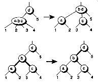
(a) Connected to the left
(b) Connected to the right
Figure 11.16 Splitting 4-nodes connected to 3-nodes.

Figure 11.17 Splitting 4-nodes connected to 3-nodes, red-black style.
struct PtrPack {RBnodeb *t, *p, *g, *gg, *s, *rs, *ls, *m, *pm;
} ;
template<class TYPE>
RBnode<TYPE> *RBtree<TYPE>::Add(const TYPE &x, int &exists)
// Add the key x to the tree if it doesn't already exist.
// Returns a pointer to the node containing the key, and
// sets the exists flag accordingly.
{PtrPack pp;
int side;
exists = 1;
pp.t = root; pp.p = 0; pp.g = 0; pp.gg = 0;
while(pp.t && x ! = ((RBnode<TYPE> *)(pp.t))->info) {// If on a 4-node, we must split it into two 2-nodes
if ((pp.t->left && pp.t->Left( )->color == RED) &&
(pp.t->right && pp.t->Right( )->color == RED)) {pp.t->color = RED;
pp.t->Left( )->color = BLACK;
pp.t->Right( )->color = BLACK;
// Check for two reds in a row, and adjust if so
if (pp.p && pp.p->color == RED)
root = (RBnode<TYPE> *)InsBalance(root, pp);
// else Figure 11.15 or Figure 11.17(a)
}
pp.gg = pp.g; pp.g = pp.p; pp.p = pp.t;
if (x < ((RBnode<TYPE> *)(pp.t))->info) {pp.t = pp.t->Left( ); side = 0;
}
else {pp.t = pp.t->Right( ); side = 1;
}
}
// Reached the bottom, with no matching node
if (pp.t == 0) {exists = 0;
pp.t = AllocNode(x, RED);
if (pp.t == 0) return 0; // Couldn't add
if (pp.p) {if (side) pp.p->right = pp.t; else pp.p->left = pp.t;
}
else root = (RBnode<TYPE> *)(pp.t);
// Check for two reds in a row, and adjust if so
if (pp.p && pp.p->color == RED)
root = (RBnode<TYPE> *)InsBalance(root, pp);
}
root->color = BLACK; // Root always made black
return (RBnode<TYPE> *)(pp.t);
}
// Define some macros for convenience
#define T (pp.t)
#define P (pp.p)
#define G (pp.g)
#define GG (pp.gg)
#define S (pp.s)
#define RS (pp.rs)
#define LS (pp.ls)
#define M (pp.m)
#define PM (pp.pm)
RBnodeb *InsBalance(RBnodeb *root, PtrPack &pp)
// Balance adjusting for top-down insertions. Eliminates
// both p and t from being red by doing rotations and
// color changes. g, p, t are assumed not null coming in.
// gg may be null. At the end of this routine, only t
// and p will be valid with respect to each other. g and gg will
// not reflect the proper ordering.
RBnodeb *cofgg; // New child of great-grandparent
int side;
side = GG && GG->right == G;
if (G->left == P) {if (P->right == T) { // Do double rotate. (Figure 11.17(c))G->left = T->right;
T->right = G;
P->right = T->left;
T->left = P;
P = GG;
cofgg = T;
}
else { // Do single rotate right. (Figure 11.17(b) reversed)G->left = P->right;
P->right = G;
cofgg = P;
}
}
else { // G->right == pif (P->left == T) { // Do double rotate. (Figure 11.17(c) reversed)G->right = T->left;
T->left = G;
P->left = T->right;
T->right = P;
P = GG:
cofgg = T;
}
else { // Do single rotate left. (Figure 11.17(b))G->right = P->left;
P->left = G:
cofgg = P;
}
}
cofgg->color = BLACK;
G->color = RED;
if (GG) {if (side) GG->right = cofgg; else GG->left = cofgg;
}
else root = cofgg;
return root;
}
Deleting from a Red-Black Tree
Figure 11.18 Building a red-black tree.
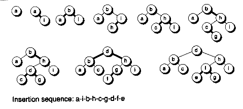
Figure 11.19 Sample top-down deletion transformations.

(a) Merging nodes

(b) 2-3-4 rotation
Figure 11.20 Case 1: Merging 2-nodes into a 4-node.

template<class TYPE>
RBnode<TYPE> *RBtree<TYPE>::Detach(const TYPE &x)
// Detaches (but does not free) the node having key x from the tree
{struct PtrPack pp;
if (root == 0) return 0;
pp.t = root; pp.p = 0; pp.g = 0; pp.m = 0; pp.pm = 0;
while (pp.t) {// Go down the tree one level, searching for node to delete
if ( ((RBnode<TYPE> *)(pp.t))->info == x ) {pp.m = pp.t; // Record matching node
pp.pm = pp.p; // And its parent
}
// Update ancestor pointers
pp.g = pp.p; pp.p = pp.t;
if (x < ((RBnode<TYPE> *)(pp.t))->info) {pp.t = pp.p->Left( ); pp.s = pp.p->Right( );
}
else {pp.t = pp.p->Right( ); pp.s = pp.p->Left( );
}
if (pp.s) {pp.ls = pp.s->Left( ); pp.rs = pp.s->Right( );
}
else {pp.ls = 0; pp.rs = 0;
}
root = (RBnode<TYPE> *)DelBalance(root, pp);
} // end of while loop
root = (RBnode<TYPE> *)DoReplacement(root, pp);
if (root) root->color = BLACK;
return (RBnode<TYPE> *)pp.m; // Node to delete
}
RBnodeb *DelBalance(RBnodeb *root, PtrPack &pp)
// Balancing code during top-down deletion
{if ((T == 0 | | T->color == BLACK) && S && S->color == RED) {// Case 2: t black, s red. t might be null,
// but s and p must not be. Flip the orientation
// of the 3-node that s is a part of.
// Fix g child to be s. Also s may become p of m
if (G) {if (G->left == P) G->left = S; else G->right - S;
}
else root = S;
if (P == M) PM = S;
// Finish rotating
if (P->left == T) { // Figure 11.21(a)// RotateLeftt(p);
P->right = LS;
S->left = P;
G = S;
S = LS;
}
else { // Figure 11.21(b)// RotateRight(p);
P->left = RS;
S->right = P;
G = S;
S = RS;
}
// Fix children of s
if (S) { LS = S->Left( ); RS = S->Right( ); }// Fixup colors
P->color = RED; G->color = BLACK;
}
if (T && T->color == BLACK &&
(T->left == 0 || T->Left( )->color == BLACK) &&
(T->right == 0 || T->Right( )->color == BLACK)) {if (S && S->color == BLACK &&
(S->left == 0 || S->Left( )->color == BLACK) &&
(S->right == 0 || S->Right( )->color == BLACK)) {// Case 1: t and s are black 2-nodes. Merge them
// into a 4-node. (Figure 11.20.)
P->color = BLACK; T->color = RED; S->color = RED;
}
else if (LS && LS->color == RED) {// Case 3: t is a black 2-node, s is 3- or 4-node,
// LS is red (RS might be). Rotate 3- or 4-node to
// the side that t is on.
if (P- >left == T) { // Figure 11.22(b)// Fix colors
LS->color = P->color; P->color = BLACK; T->color = RED;
// Fix g child to be LS. Also LS may become p of m.
if (G) {if (G->left == P) G->left = LS; else G->right = LS;
}
else root = LS;
if (P == M) PM = LS;
// Finish: DoubleRotateLeft(s, p)
P->right = LS->left;
LS->left = P;
S->left = LS->right;
LS->right = S;
G = LS;
// We won't fix s and children since they get re-assigned
// at the top of next loop
}
else { // Figure 11.22(b)// Fix colors
S->color = P->color; LS->color = BLACK;
P->color = BLACK; T->color = RED;
// Fix g child to be s. Also s may become p of m.
if (G) {if (G->left == P) G->left = S; else G->right = S;
}
else root = S;
if (P == M) PM = S;
// Finish: RotateRight(p);
P->left = RS;
S->right = P;
G = S;
// We won't fix s and children since they get re-assigned
// at the top of next loop
}
}
else if (RS && RS->color == RED) {// Case 3: t is a 2-node, s is a 3-node, LS black, RS red
// Rotate 3-node to the side of t
if (P->left == T) { // Figure 11.22(b)// Fix colors
RS->color = BLACK; S->color = P->color;
P->color = BLACK; T->color = RED;
// Fix g child to be s. Also, s may become p of m.
if (G) {if (G->left == P) G->left = S; else G->right = S;
}
else root = S;
if (P == M) PM = S;
// Finish: RotateLeft(p);
P->right = LS;
S->left = P;
G = S;
// We won't fix s and children, since they get reassigned
// at the top of next loop
}
else { // Figure 11.22(d)// Fix colors
RS->color = P->color; P->color = BLACK; T->color = RED;
// Fix g child to become RS. Also, RS may become p of m.
if (G) {if (G->left == P) G->left = RS; else G->right = RS;
}
else root = RS;
if (P == M) PM = RS;
// Finish: DoubleRotateRight(s, p);
P->left = RS->right;
RS->right = P;
S->right = RS->left;
RS->left = S;
G = RS;
// We won't fix s and children, since they get reassigned
// at the top of next loop
}
}
}
return root;
}
RBnodeb *DoReplacement(RBnodeb *root, PtrPack &pp)
{// At this point, m is the node to delete, pm is its parent,
// p is the replacement node, g is its parent. If m has no
// successor, p will = m, and replacement is the non-null
// child of m.
if (M) { // Matching node was foundif (P == M || M->left == O || M->right == O) {// No successor, and/or at least one child null
// Get non-null child, if any; else p will be null
P = (M->left) ? M->Left( ) : M->Right( );
}
else { // m has a successor to use as a replacementif (G != M) {// Successor isn't immediate child of m, so detach
// from where it is, attach to where m is
G->left = P->right;
P->right = M->right;
}
// Finish attaching where m is
P->left = M->left;
}
// p should have same color as m since it's going where m was
if (P) P->color = M->color;
}
// Fix pm child link to be p
if (M) {if (PM) {if (PM->left == M) PM->left = P; else PM->right = P;
}
else root = P; // New root, possibly null
}
return root;
}
Figure 11.21 Case 2: Reorienting a 3-node.
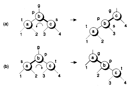
Figure 11.22 Case 3: Rotating 2-3-4 trees in red-black form.

BOUNDARY CONDITIONS
Figure 11.23 Removing nodes from a red-black tree.
SUMMARY


