


A Sequence diagram models a dynamic view of the interactions between model elements at runtime.
Sequence diagrams are commonly used as explanatory models for Use Case scenarios. By creating a Sequence diagram with an Actor and elements involved in the Use Case, you can model the sequence of steps the user and the system undertake to complete the required tasks. An element in a Sequence diagram is usually either an Actor (the stimulus that starts the interaction) or a collaborating element.
Note: A Sequence diagram is often attached directly under the Use Case to which it refers. This helps keep elements together, both in the model and when documentation is produced. To do this, right-click the Use Case on the diagram and select Advanced | Composite Element.
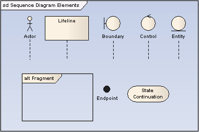
The example below shows some possible elements of Sequence diagrams and their stereotyped display.
| · | Actor - An instance of an actor at runtime. |
| · | Lifeline - An Object element with the stereotype Lifeline. |
| · | Boundary - Represents a user interface screen or input/output device |
| · | Entity - A persistent element - typically implemented as a database table or element. |
| · | Control - The active component that controls what work gets done, when and how. |
Tip: Use Sequence diagrams early in analysis to capture the flow of information and responsibility throughout the system. Messages between elements eventually become method calls in the Class model.
See Also