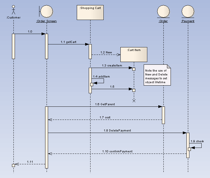
A Sequence diagram is a structured representation of behavior as a series of sequential steps over time. It is used to depict work flow, message passing and how elements in general cooperate over time to achieve a result.
| · | Each sequence element is arranged in a horizontal sequence, with messages passing back and forward between elements. |
| · | An Actor element can be used to represent the user initiating the flow of events. |
| · | Stereotyped elements, such as Boundary, Control and Entity, can be used to illustrate screens, controllers and database items, respectively. |
| · | Each element has a dashed stem called a lifeline, where that element exists and potentially takes part in the interactions. |
Example Diagram
The following example Sequence diagram demonstrates several different elements:

Toolbox Elements and Connectors
Select Sequence diagram elements and connectors from the Interaction pages of the Enterprise Architect UML Toolbox.
Tip: Click on the elements and connectors below for more information.
See Also
OMG UML Specification
The OMG UML specification (UML Superstructure Specification, v2.0, p. 14) states:
"A diagram that depicts an interaction by focusing on the sequence of messages that are exchanged, along with their corresponding event occurrences on the lifelines.
"Unlike a communication diagram, a sequence diagram includes time sequences but does not include object relationships. A sequence diagram can exist in a generic form (describes all possible scenarios) and in an instance form (describes one actual scenario). Sequence diagrams and communication diagrams express similar information, but show it in different ways."


